User Manual For CYCLONE FX Programmers 20
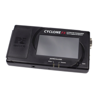
Figure 3-22: Communications Mode Selection
3.19.8.2.1 High-Performance Communications
If high-performance options are available for the selected device they will appear in the “Shift
Frequency in MHz” drop-down. CYCLONE FX programmers are capable of high-performance
communications when using certain ARM Cortex targets in SWD mode.
Figure 3-23: High-Performance Options
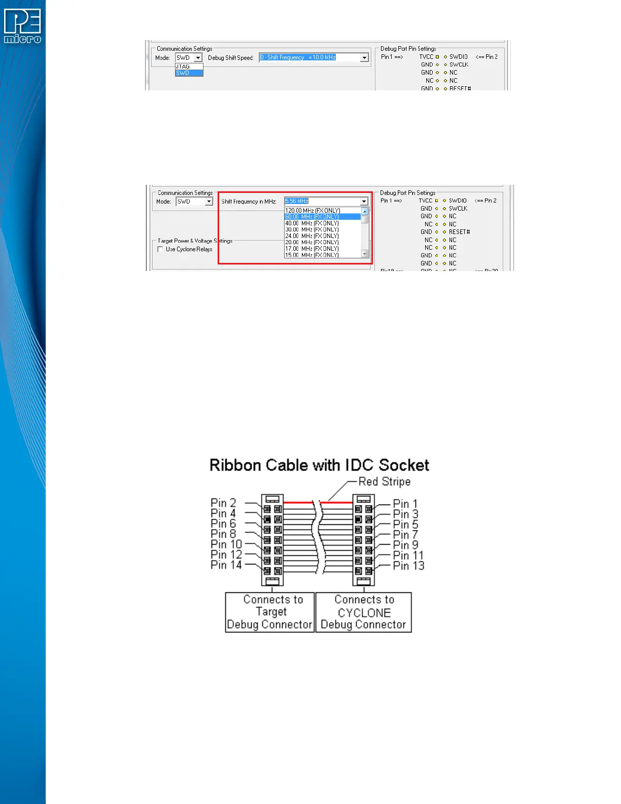
3.20 Ribbon Cable
CYCLONE FX programmers communicate with the target through ribbon cables. The ribbon
cables for standard debug connectors have a 0.100-inch centerline dual row socket IDC assembly
(not keyed). The ribbon cables for 10- and 20-pin mini debug connectors have a 0.050-inch
centerline dual row socket IDC assembly (keyed). The ribbon cables are designed such that the
Cyclone’s Debug Connector has the same pinout as the Target Header, i.e., Pin 1 of the Cyclone’s
Debug Connector is connected to Pin 1 of the Target Header. As an example, Figure 3-24
sketches the connection mechanism (looking down into the sockets) for a 14-pin ribbon cable.
Ribbon cables for other supported architectures use a similar scheme, but may have more or
fewer pins.
Figure 3-24: Ribbon Cable Example Diagram, When Looking Into IDC Socket
 Loading...