~
i/e" LO~/ HEIGHT NUT
,,
// @-__
....
"
I I ,’ ’,
2 IN, SQ, END CAP~
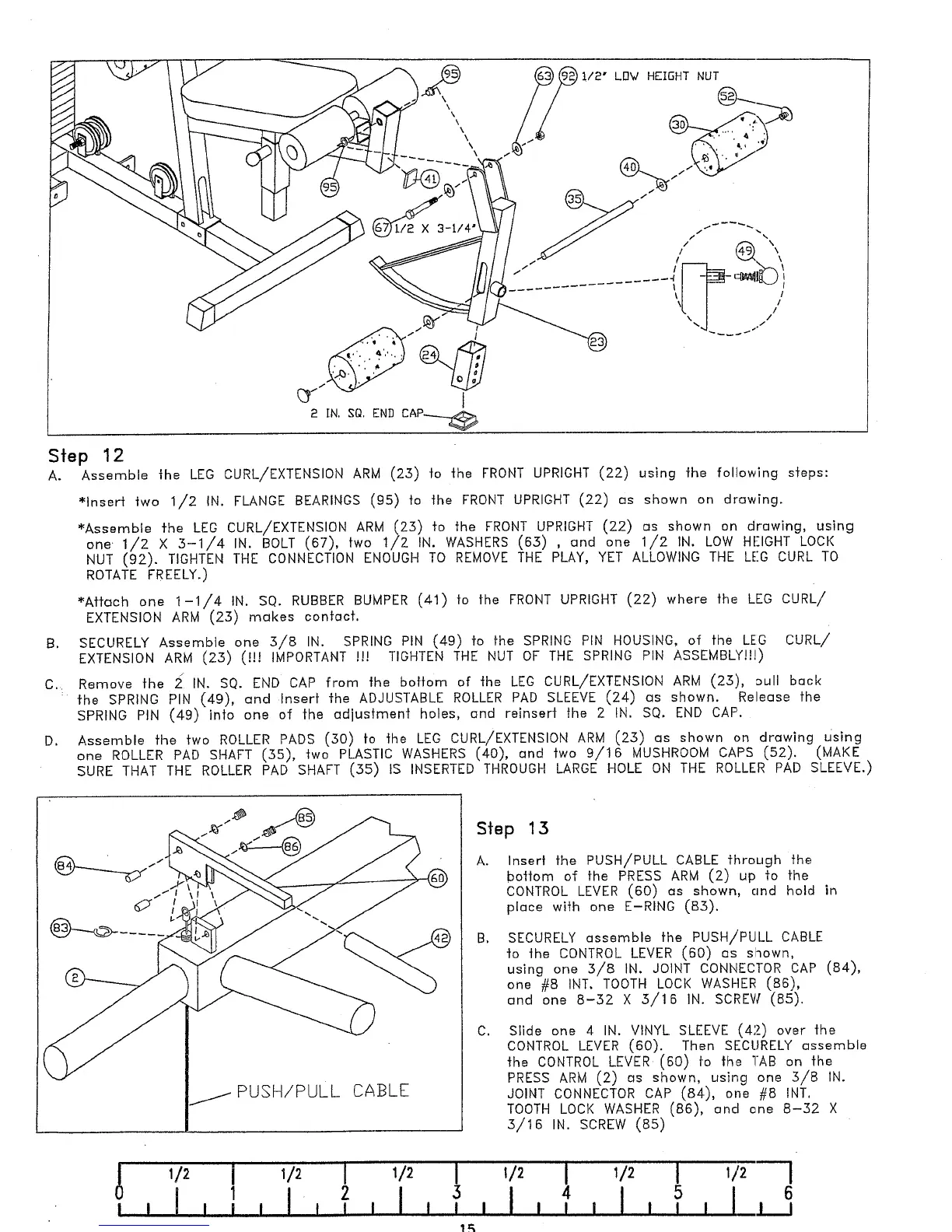
Step 12
A.
Assemble the LEG CURL/EXTENSION ARM (25) to the FRONT UPRIGHT (22) using the follow;ng steps:
~lnsert two 1/2 IN. FLANGE BEARINGS (95) to the FRONT UPRIGHT (22) es shown on drewing.
~Assemble the LEG CURL/EXTENSION ARM (25) to the FRONT UPRIGHT (22) r~s shown on drawing, using
one 1/2 X .5-1/4 IN. BOLT (67), two 1/2 IN. WASHERS (6.5) , and one 1/2 IN. LOW HEIGHT
NUT (92). TIGHTEN THE CONNECTION ENOUGH TO REMOVE THE PLAY, YET ALLOWING THE LEG CURL
ROTATE FREELY.)
~Aff(~ch one 1-1/4 IN. SQ. RUBBER BUMPER (41) to the FRONT UPRIGHT (22) where the LEG
EXTENSION ARM (25) makes contact.
B. SECURELY Assemble one .5/8 IN. SPRING PIN (49) to the SPRING PiN HOUSING, of the LEG
CURL/
EXTENSION ARM (25) (!!! IMPORTANT !!! TIGHTEN THE NUT OF THE SPRING PIN ASSEMBLY!!!)
C.. Remove the ~ IN. SQ. END CAP from the bottom of the LEG CURL/EXTENSION ARN (25), 3ull back
: the SPRING PIN (49), and Insert the ADJUSTABLE ROLLER PAD SLEEVE (24) es shown. Release
SPRING PIN (49) into one of the adiusfment holes, and reinsert the 2 IN. SQ. END CAP.
D.
Assemble the two ROLLER PADS (50) to the LEG CURL/EXTENSION ARM (2.5) as shown on drawing Using
one ROLLER PAD SHAFT (55), two PLASTIC WASHERS (40), Grid two 9/16 MUSHROOM CAPS (52).
SURE THAT THE ROLLER PAD SHAFT (55) IS INSERTED THROUGH LARGE HOLE ON THE ROLLER PAD SLEEVE.)
PUSH/PULL CABLE
Step 13
Inser! the PUSH/PULL CABLE through the
bottom of the PRESS ARM (2) up to the
CONTROL LEVER (60) as shown, cmd hold
piece with one E-RING (83).
SECURELY assemble the PUSH/PULL CABLE
to the CONTROL LEVER (60) os shown,
using one 5/8 IN. JOINT CONNECTOR CAP (84),
one #8 INT. TOOTH LOCI< WASHER (86),
end one 8-52 X 5/16 IN. SCREVl (85).
Slide one 4 IN. VINYL SLEEVE (42_) over the
CONTROL LEVER (60). Then SECURELY assemble
the CONTROL LEVER (60) fo the TAB on the
PRESS ARM (2) as shown, using one 5/8 IN.
JOINT CONNECTOR CAP (84), one #8 INT.
TOOTH LOCK WASHER (86), end one 8-52
S/16 ~N. SCREW (SS)
I
1/2
I
1/2
I
5 64
I | I
I I_1 II !
i
 Loading...