FIGURE
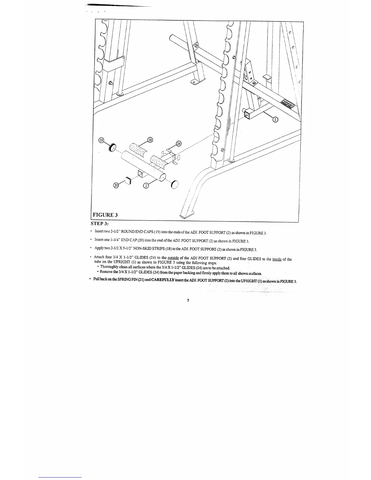
STEP 3:
¯
Insert two 2-1/2’ ROUND END CAPS (19) into the ends of the .ADJ. FOOT SUPPORT (2) as shown in FIGURE
¯
Insert one I-3/4" ENiD CAP (20) into the end ofthe ADJ. FOOT SUPPORT (2) as shown in FIGURE
¯
Apply m’o 2-1/2 X 5-1/2" NON-SKID STRIPS (18) to the ADJ. FOOT SUPPOKI" (2) as sho~n in FIGL~q.E
¯
Attach four 3/4 X 1-I/2" GLIDES (24) to the outside of the .4~DJ FOOT SUPPORT (2) and four GLIDES to the inside of the
tube on the UPRIGHT (1) as showrt in FIGURE 3 using the follo~ng steps:
¯
Thoroughly clean all surfaces where the 3/4 X 1-112" GLIDES (24) are to be attached.
¯
Remove the 3/4 X I o 1/2" GLIDES (24) from the paper backing and firmly apply them to all show~l srxfaees.
¯ Pull back on the SPRING PIN (21 ) and CAREFIILLY insert the AD I. FOOT SUPPOKr (2) into the UPRIGHT (1) as shown in FIGURE 3.
 Loading...