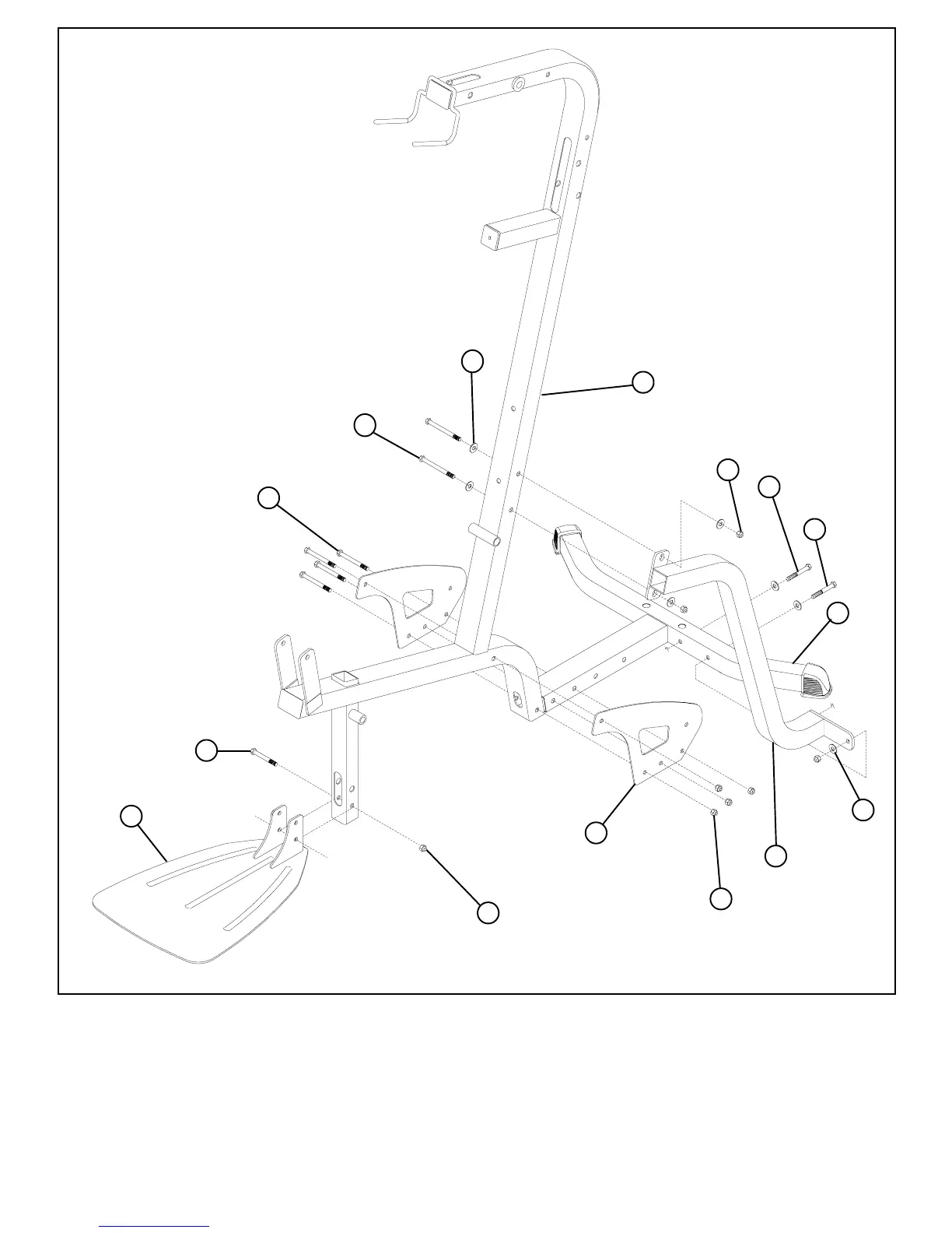
FIGURE 1
6
STEP 1:
1
34
30
2
62
3/8 X 3
29
34
3
• LOOSELY assemble two BASE PLATES (3) to the FRAME (1) and BASE (2) using four 3/8 X 3-3/4” BOLTS (30)
and four 3/8” LOCK NUTS (34). See FIGURE 1.
34
63
3/8 X 4
36
• LOOSELY assemble the FOOTPLATE (62) to the lower holes in the FRAME (1) using one 3/8 x 3” BOLT (29) and one
3/8 LOCKNUT (34)
36
29
• LOOSELY assemble the TOP of FRAME BRACE (64) to the FRAME (1) using two 3/8 x 4” BOLT (63), two 3/8 WASHERS
(36) and two 3/8 LOCKNUTS (34) Assemble BOTTOM of FRAME BRACE (64) to FRAME (2) using one 3/8 x 3” BOLT
(29), one 3/8 x 2-1/2” BOLT (28) three 3/8 WASHERS (36) and one 3/8 LOCKNUT (34)
3/8 X 3
28
3/8 X 2-1/2
3/8 X 3-3/4
64