9
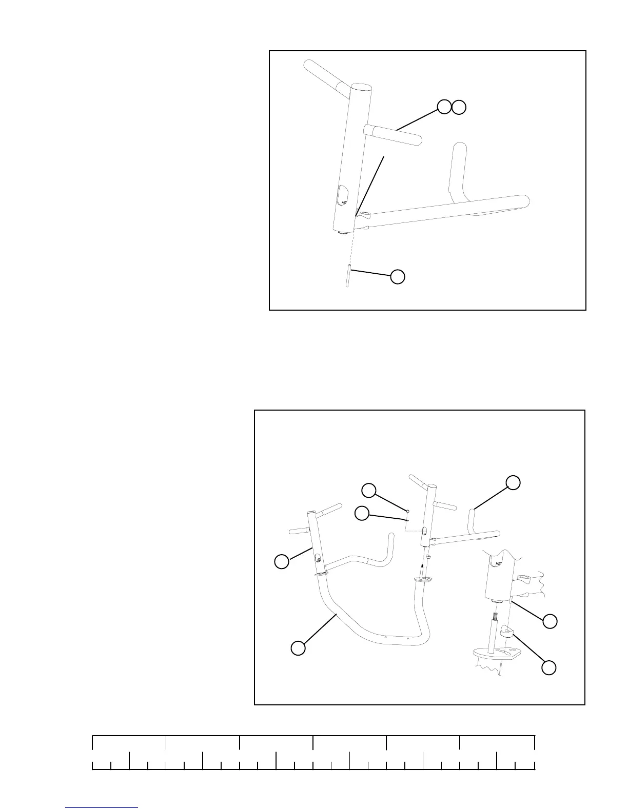
STEP 7:
• Using hammer tap one 5/16 X 2” ROLL PIN (47)
thru LEFT PRESS HANDLE (7) until it is flush
with other side of HANDLE as shown in
FIGURE 6
8
6
7
FIGURE 6
STEP 6:
• Place LEFT PRESS HANDLE (7) onto PRESS
ARM (8). Place PRESS ARM SPACER (65) as
shown over 5/6 x 2 ROLL PIN (47), make sure
that the 5/16 X 2” ROLL PIN (47) passes into
the slot located in the plate of the PRESS ARM
(8)
FIGURE 7
7
36
34
47
6
• Once in place secure and tighten the LEFT
PRESS HANDLE (7) to PRESS ARM (8)
using one 3/8” WASHER (36) and one
3/8” LOCK NUT (34)
0
1
2
345
6
1/2 1/2 1/2 1/2 1/2 1/2
NOTE:
Place PRESS ARM (8) upside down on floor as shown to complete this step.
HANDLES (7) MUST BE PLACED TOWARDS INSIDE OF PRESSARM
47
• Repeat STEP 6 for the RIGHT PRESS
ARM HANDLE (6)
• Repeat STEP 7 for the RIGHT PRESS
ARM HANDLE (6)
FLUSH SIDE
• IMPORTANT! Do not overtighten: PRESS
ARM should rotate freely
65