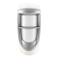
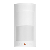
2 Digigard DG85
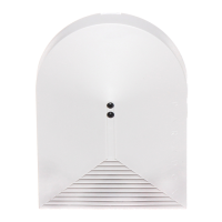
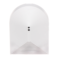
PCB Height Adjustment
The DG85 is designed for optimal performance
at a height of 2.1m (7ft), but can be installed
lower or higher. After you have installed the
detector, ensure that the adjustable height
markings on the upper right of the PCB’s cover
inside the unit match the installation height.
For example, if the detector is installed at a
height of 2.1m (7ft), the PCB should then be
adjusted to 2.1m (7ft). Align the desired marking
(height) with the back cover’s plastic tab (Figure
1 on page 25 and Figure 2 on page 26).
If another installation height is called for, readjust
the PCB accordingly. Any PCB adjustments
should be followed by a walk-test of the
protected area. Walk-testing verifies that the
required coverage is in place.
Ensure that the unit’s front and back
cover are tightly joined together without
any spacing (around the rim of the unit)
before tightening the screw, otherwise
the weatherproof casing may be
compromised and moisture may enter
the unit.
Operational Modes
Digigard DG85 can function in two different
operational modes: DGP2 Mode or Relay Mode.
This option can only be configured using the DIP
switches.
DG85_TI04.fm Page 2 Tuesday, February 15, 2005 9:17 AM
 Loading...