4 Complete Installation Manual
2.8 ZONE INPUTS
Detection devices such as motion detectors and door contacts are connected to the control panel's zone input terminals labelled Z1, Z2, Z3, Z4
and
FIRE as shown in Figure 8-2: Zone Connections on page 14. Once the zones are connected, the associated zone's parameters must be
defined. For more information, please refer to
Zone Programming on page 5.
The
FIRE input, which is recognized as zone 6, can be connected as a fire zone or a 24-hour burglary zone. Fire zones must use a 1kΩ EOL
resistor. If a line short occurs or if the smoke detector becomes active, whether the system is armed or disarmed, the control panel will generate
an alarm on this zone.
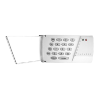
2.9 KEYPAD INSTALLATION
Only the 1686V and the 1686H Spectra Keypads are compatible with the Spectra 1727 control panel. Remove the keypad’s back cover and wire
the
GRN, YEL, RED, and BLK terminals to the corresponding terminals on the control panel as shown in Figure 8-1: PCB Layout on page 13.
2.10 KEYPAD ZONE INSTALLATION
The keypad has one zone input terminal that allows you to connect one motion detector or one door contact directly to the keypad. The keypad
zone is recognized as zone 5. Only one keypad zone can be used per Spectra 1727 control panel. The keypad communicates the status of the
keypad zone to the control panel once the device is connected as shown in Figure 8-1: PCB Layout on page 13 and the zone’s parameters are
defined (see section 3.2). For example, a door contact located at the front door can be wired directly to the input terminal of the keypad instead of
wiring it back to the control panel.
2.11 KEYPAD TAMPER
If the keypad has a tamper switch, the state of the tamper is displayed on zone 5. The control panel cannot differentiate between the open
keypad zone and an open keypad tamper.
Table 1: PGM Events
PGM Event Description
Exit Delay
The PGM activates during the Exit Delay.
Armed
The PGM activates while the system is armed.
Ready
The PGM activates while the READY LED is illuminated.
“PG” Key
The PGM activates when the PG key is pressed and deactivates when the key is pressed again.
Fire Alarm
The PGM activates during a Fire Alarm.
Audible Alarm
The PGM activates during any alarm.
Strobe
The PGM activates while the ARM LED flashes in alarm.
Entry Delay/Exit Delay/Alarm
The PGM activates during the Entry Delay, the Exit Delay and during an alarm.
Exit Delay/Armed
The PGM activates during the Exit Delay or while the system is armed.
Entry Delay/Alarm
The PGM activates during the Entry Delay or during an alarm.
Regular Armed
The PGM activates while the system is Regular Armed.
Table 2: PGM Options
Option
PGM 1 Events
First Digit
PGM 2 Events
Second Digit
[0]
Exit Delay Exit Delay
[1]
Armed Armed
[2]
Ready Ready
[3]
“PG” Key “PG” Key
[4]
Fire Alarm Fire Alarm
[5]
Alarm Alarm
[6]
Strobe Strobe
[7]
Entry Delay/Exit Delay/Alarm Entry Delay/Exit Delay/Alarm
[8]
Exit Delay/Armed Entry Delay/Alarm
[9]
Regular Arming Entry Delay/Alarm
 Loading...