BASIC Stamp II Manual 0.94 • Parallax, Inc. • (916) 624-8333 • Page 59
BASIC Stamp II
SEROUT tpin,baudmode,{pace,}[outputdata]
SEROUT tpin\fpin,baudmode,{timeout,tlabel,}[outputdata]
Output data serially.
example:
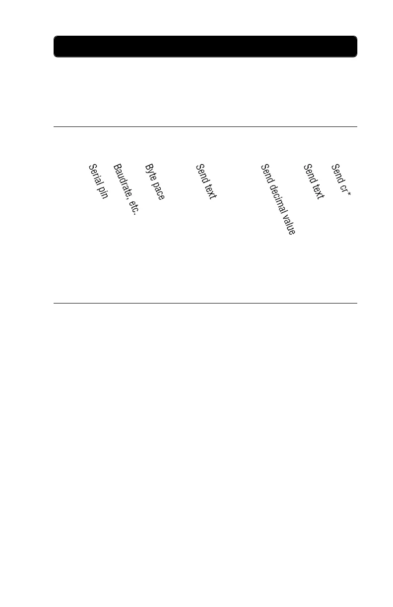
SEROUT 3,84+$4000,100,[“The temperature is ”,dec temp,“ degrees.”,cr]
Send serial data on pin 3. Transmission mode is 9,600 baud, 8 data
bits, no parity, inverted data, driven output. Transmitted bytes will be
sent at the rate of one byte every 0.1 seconds (100 milliseconds). Sample
output would look like this: “The temperature is 75 degrees.”
Tpin is 0-15 for an I/O pin, or 16 for the internal serial port (pin 1, TX).
If a regular I/O pin is used, then the output will be on a TTL-level pin.
If the TX pin is used, then the output will be on a pseudo-RS232 pin.
The difference is this:
On a TTL-level pin (0-15), the signals sent are 0 to 5 volts. Serial
communication with TTL signals should work well for most
applications (certainly if the communicating devices are all TTL-
level). However, if the device receiving serial data requires real RS232
voltages, then it may not accept data from a TTL pin on the Stamp II.
On the RS232-level pin (16), the signals sent are RX to 5 volts. This
may seem a bit confusing, but this is how the circuit works: for
sending a low signal, the Stamp II reflects the “rest” (low) state of
the RX pin, which is usually about -10 volts; for sending a high
signal, the Stamp II uses 5 volts. This system only works if the
serial device to which the Stamp II is connected has “real” +/-
voltage generation circuitry. Real RS232 voltages are standard on
most serial devices, such as PCs, printers, modems, etc.
* carriage
return