BASIC Stamp II Manual 0.94 • Parallax, Inc. • (916) 624-8333 • Page 7
BASIC Stamp II
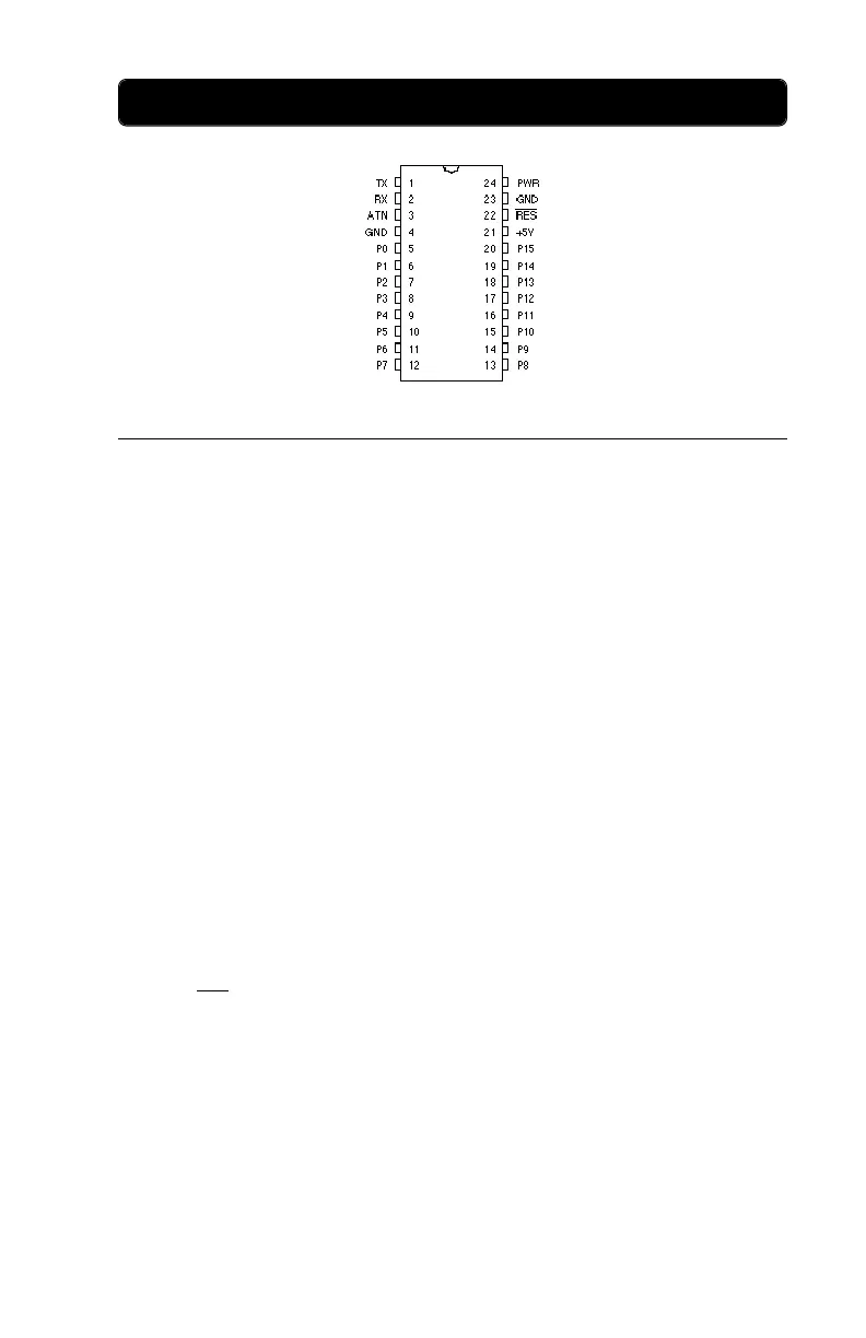
Pin Name Description Comments
1 TX Serial output Connect to pin 2 of PC serial DB9 (RX) *
2 RX Serial input Connect to pin 3 of PC serial DB9 (TX) *
3 ATN Active-high reset Connect to pin 4 of PC serial DB9 (DTR) *
4 GND Serial ground Connect to pin 5 of PC serial DB9 (GND) *
5 P0 I/O pin 0 Each pin can source 20 ma and sink 25 ma.
6 P1 I/O pin 1
7 P2 I/O pin 2 P0-P7 and P8-P15, as groups, can each
8 P3 I/O pin 3 source a total of 40 ma and sink 50 ma.
9 P4 I/O pin 4
10 P5 I/O pin 5
11 P6 I/O pin 6
12 P7 I/O pin 7
13 P8 I/O pin 8
14 P9 I/O pin 9
15 P10 I/O pin 10
16 P11 I/O pin 11
17 P12 I/O pin 12
18 P13 I/O pin 13
19 P14 I/O pin 14
20 P15 I/O pin 15
21 +5V ** +5V supply 5-volt input or regulated output.
22 RES Active-low reset Pull low to reset; goes low during reset.
23 GND System ground
24 PWR ** Regulator input Voltage regulator input; takes 5-15 volts.
* For automatic serial port selection by the Stamp II software, there must also be a connection
from DSR (DB9 pin 6) to RTS (DB9 pin 7). This connection is made on the Stamp II carrier
board. If you are not using the carrier board, then you must make this connection yourself, or
use the command-line option to tell the software which serial port to use.
** During normal operation, the Stamp II takes about 7 mA. In various power-down modes, con-
sumption can be reduced to about 50 µA.