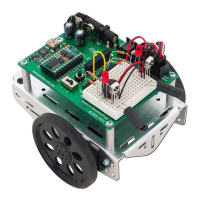
Page 8 · SumoBot – Mini Sumo Robotics
Step #11
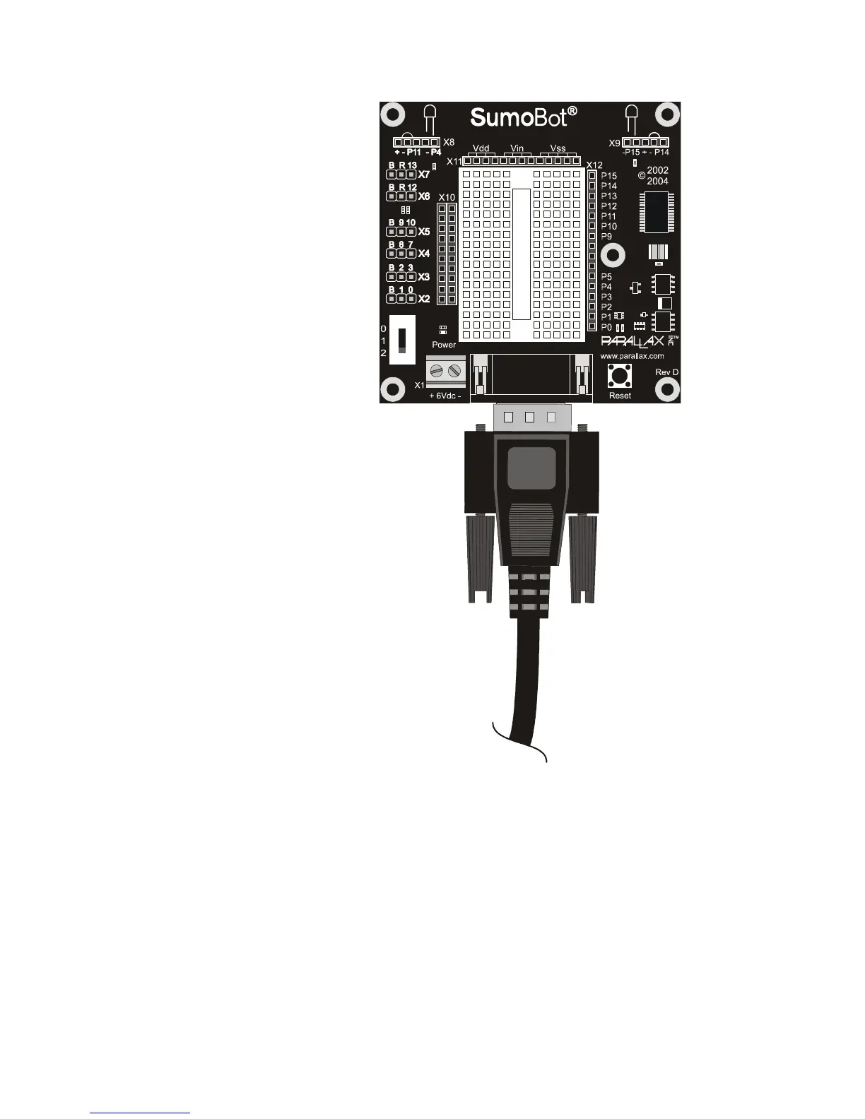
Make the Connections
Plug the servo motors and QTI
sensors into the SumoBot PCB
connectors as indicated below.
Note that the "B" pin on each
connector is for the black wire.
X7 = Left Servo Motor
X6 = Right Servo Motor
X5 = Left QTI Line Sensor
X4 = Right QTI Line Sensor
Connect the battery pack wires to
SumoBot PCB connector X1.
The battery pack's white-striped
lead connects to the
+ terminal.
Note: Previous versions of the SumoBot PCB
were labeled "SumoBoard" instead of
"SumoBot." These boards are electrically
identical to the SumoBot PCB illustrated.
When using SumoBot PCBs with a revision
code of C or earlier, the Vs1 and Vs2 (servo
ground) connections must be jumpered to
Vss for proper servo operation.
 Loading...