Page 26 · SumoBot – Mini Sumo Robotics
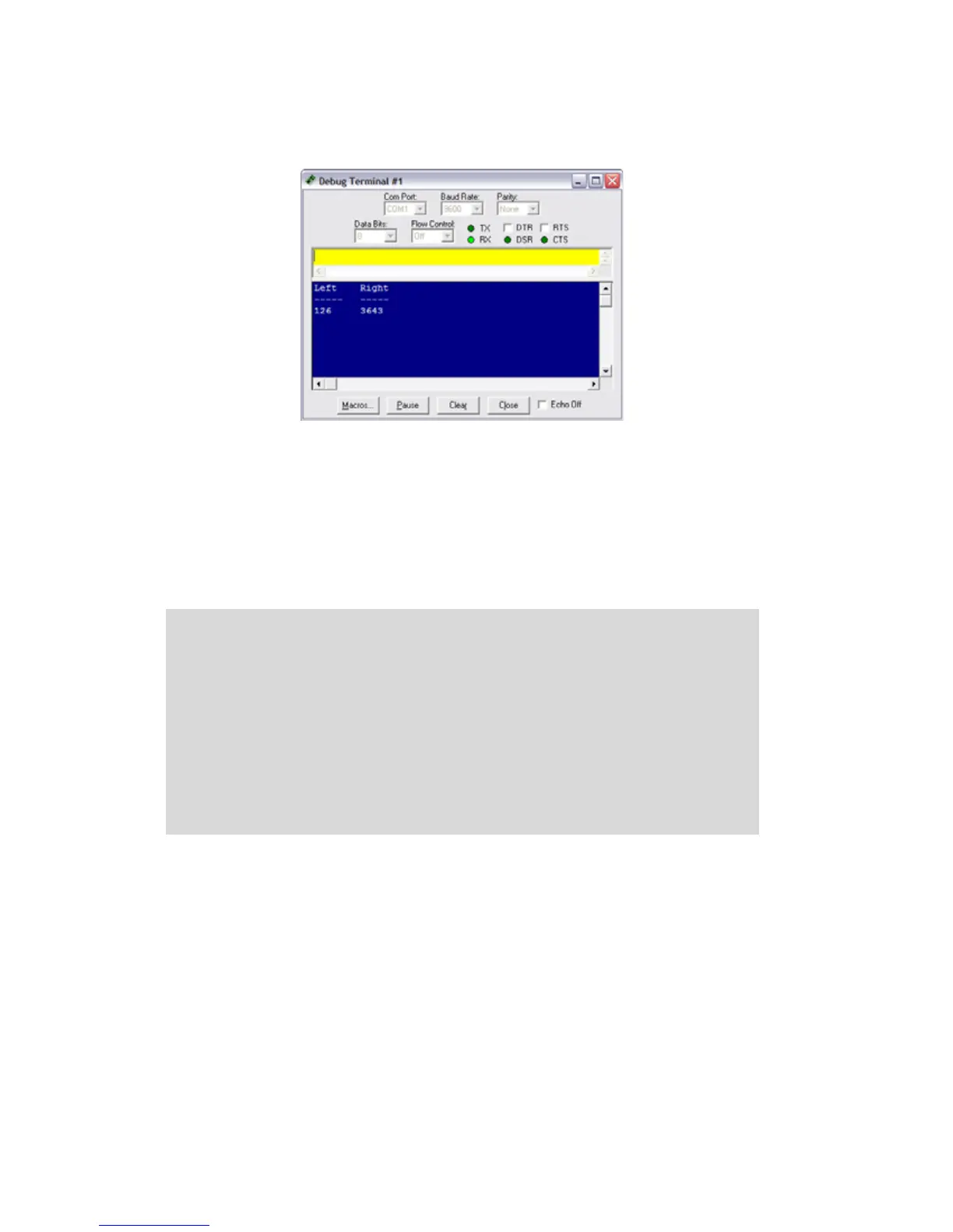
Figure 3.2: QTI Test Program Output
Don't worry about small discrepancies between the QTI values over the same color – this
is due to minor variations in components and won't adversely affect the SumoBot robot’s
performance.
For convenience in a competition program, the QTI code should be moved into a
subroutine that can be called from any point in the program. The routine should also be
developed to return either a True (1) or False (0) value if the QTI is over the Sumo ring
border. To see this in action, load and run program 3.2.
' Mini_Sumo_3.2_Line_Sensor_Read.BS2
' {$STAMP BS2}
' {$PBASIC 2.5}
' -----[ I/O Definitions ]-------------------------------------------------
LLinePwr PIN 10 ' left line sensor power
LLineIn PIN 9 ' left line sensor input
RLinePwr PIN 7 ' right line sensor power
RLineIn PIN 8 ' right line sensor input
' -----[ Variables ]-------------------------------------------------------
lLine VAR Word ' left sensor raw reading
rLine VAR Word ' right sensor raw reading
lineBits VAR Nib ' decoded sensors value
 Loading...