22
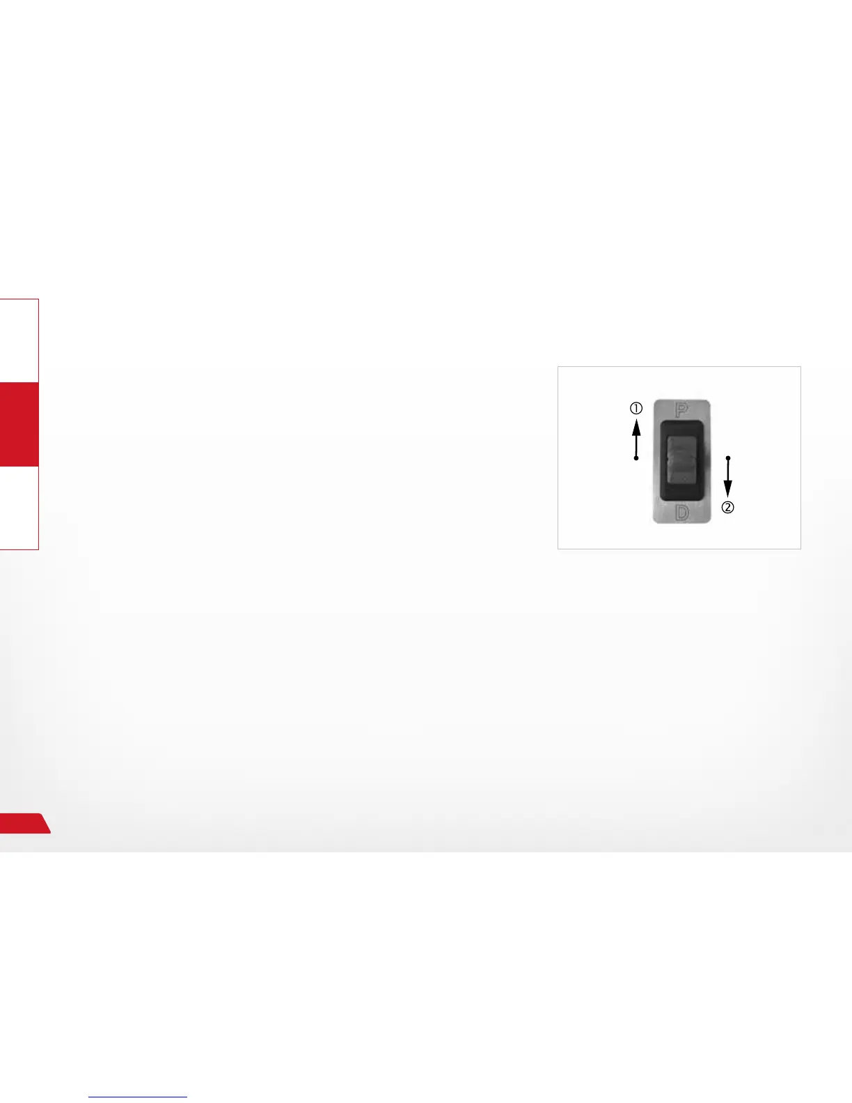
Fig. 13: Shift diagram
Shifting diagram of gear control with emergency switch
The servo motor for the automatic transmission shifts through
the driving gears from the "P" position in the direction of "D"
due to activation of the toggle switch.
This means the driving gears are selected and shifted in sequence
through the
› pressing and holding of the rocker switch in the "D" direction
→ R, N, D (manual STOP! back with )
Selecting again causes a further shift into sub-gears 1, 2, and
3 of driving gear "D". The sub-gears cannot be selected during
emergency operation.
› pressing and holding of the rocker switch in the "P" direction
→ D, N, R, and P (manual STOP! forward with )