Bulletin HY25-1806-M1/US
Owner’s Manual
252 Series
Parker Hannifin Corporation
Chelsea Products Division
Olive Branch, MS 38654 USA
10
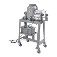
4. Install the proper studs (379428-14 furnished with
PTO) in the PTO aperture pad. The stud kit
furnished with the PTO contains five (5) studs and
one (1) cap screw and have pre-applied locking/
sealing compound. Do not install a stud in the
top hole on the aperture pad, this is for the
cap screw (See Fig. 6) for proper placement
of studs. Tighten studs securely and torque to
17-19 Lbs-ft (23.05-25.76 Nm).
CAUTION: Over tightening of studs may damage stud
and/or transmission threads.
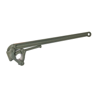
5. Place the gasket (35-P-41) provided with the
PTO over the studs (Fig. 7). Only one
gasket is required because the 252 Series
PTO does not require the backlash to be set.
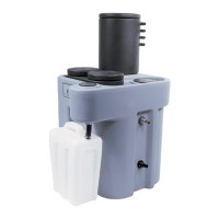
6. Secure the PTO & Pump to the transmission.
Install the long bolt to the top hole in the PTO
and the flange nuts (provided with the PTO) to
the studs (Fig. 8).
NOTE: Flange nuts do not require lock washers.
7. Fasten the Power Take-Off to the transmission.
Torque the five (5) flange nuts (379744) to
35-40 Lbs-ft [47-54 Nm].
Torque the cap screw (379578-48) to 30-35 Lbs-ft
[41-47 Nm]
Fig. 6
Fig. 7
Fig. 8
PTO Installation
GM 3600 Chassis (Continued)
Allison Installation

 Loading...