This document is a service manual for the Parker Commercial Hydraulics PGP/PGM 300 Series gear pumps and motors. It provides comprehensive information for the disassembly, assembly, and maintenance of these hydraulic units, emphasizing the importance of using genuine Parker replacement parts and maintaining cleanliness during service.
Function Description:
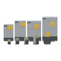
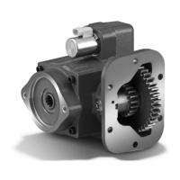
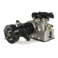
The PGP/PGM 300 Series are positive displacement gear pumps and motors designed for hydraulic systems. They operate by trapping fluid between the teeth of rotating gears and forcing it through the system. The manual illustrates both single and multiple pump configurations.
- Single Pump: Features a cast iron housing, high-temperature seals, SAE split flange and ORB ports, and SAE 2 or 4 bolt mounts. Internally, it utilizes case-hardened gears and low-friction bushing coatings.
- Multiple Pump: Designed for applications requiring multiple hydraulic circuits or increased flow. It incorporates internal passages for constant bushing lubrication, large passages for better pump feed, long shaft journals for superior bushing surfaces, a one-piece drive shaft and gear, balanced thrust plates to minimize friction and leakage, and an outboard bearing for load support on the output shaft.
Important Technical Specifications:
The manual provides detailed tool lists and specifications for various components, particularly for specialized tools required for service.
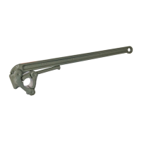
- Bushing Puller (Owatonna Tool Co. MD - 956 or equivalent): Modifications for OTC collets are provided for different pump/motor models:
- PGP/PGM 315: A: .900"/.800", B: .800"/.790", C: .100"/.090" (OTC Collect No. 33863)
- PGP/PGM 330: A: .980"/.970", B: .875"/Ref., C: .100"/.090" (OTC Collect No. 33863)
- PGP/PGM 350: A: 1.122"/1.122", B: 1.000"/0.990", C: .072"/.052" (OTC Collect No. 33864)
- PGP/PGM 365: A: 1.382"/1.372", B: 1.250"/1.250", C: .100"/.120" (OTC Collect No. 33865)
- Bushing Installation Tool (A.I.S.I 8620 Bearing Quality Steel Heat Treated):
- PGP/PGM 315: A: 2.312", B: 1.15", C Dia: .937" (+.000"/-.002"), D Dia: 1.250
- PGP/PGM 330: A: 3.000", B: 1.47", C Dia: 1.054" (+.000"/-.002"), D Dia: 1.250
- PGP/PGM 350: A: 3.000", B: 1.47", C Dia: 1.282" (+.000"/-.002"), D Dia: 1.625
- PGP/PGM 365: A: 3.000", B: 1.73", C Dia: 1.492" (+.000"/-.002"), D Dia: 1.750
- Special Steel Sleeve (for lip seal installation):
- PGP/PGM315: 1" dia. x 3-1/8" bar
- PGP/PGM330: 1-1/8" dia. x 4-5/8" bar or 1-1/4" dia. x 4-5/8" bar
- PGP/PGM350: 1-3/8" dia. x 4-5/8" bar
- PGP/PGM365: 1-1/2" dia. x 4-5/8" bar
- Dimensions for the special steel sleeve include:
- PGP/PGM 315: A: 1-7/8", B: 3", C Radius: 9/16", D Dia: .944" (+.000"/-.002"), E Dia: .885" (+.000"/-.002"), F° Chamfer: .050" x 60°
- PGP/PGM 330: A: 3-3/8", B: 4-1/2", C Radius: 9/16", D Dia: 1.065" (+.000"/-.002"), E Dia: 1.002" (+.000"/-.002"), F° Chamfer: .015" x 45°
- PGP/PGM 350: A: 3-3/8", B: 4-1/2", C Radius: 9/16", D Dia: 1.290" (+.000"/-.002"), E Dia: 1.250" (+.000"/-.002"), F° Chamfer: .015" x 60°
- PGP/PGM 365: A: 3-3/8", B: 4-1/2", C Radius: 9/16", D Dia: 1.377" (+.000"/-.002"), E Dia: 1.250" (+.000"/-.002"), F° Chamfer: .015" x 60°
- Torque Guide for Fasteners (cross-pattern):
- PGP315/PGM315: 142 Lbs-ft
- PGP330/PGM330: 200 Lbs-ft
- PGP350/PGM350: 200 Lbs-ft
- PGP3365: 200 Lbs-ft
- PGM365: 450 Lbs-ft
- Hydraulic Oil Recommendations:
- Viscosity: Optimum operating viscosity is about 100 SUS (20 cSt). Minimum: 50-60 SUS (7.5-10 cSt). Maximum at start-up: 7500 SUS (1600 cSt).
- Recommended Viscosity Grades (at 100°F/40°C and 210°F/100°C):
- ISO 32: 165 SUS (32 cSt) / 44 SUS (5 cSt)
- ISO 46: 240 SUS (46 cSt) / 49 SUS (7 cSt)
- SAE 10: 150 SUS (32 cSt) / 41 SUS (4 cSt)
- SAE 20: 300 SUS (71 cSt) / 51 SUS (7 cSt)
- Other Desirable Properties: Viscosity Index: 90 minimum, Aniline Point: 175 minimum.
- Additives Usually Recommended: Rust and Oxidation (R & O) Inhibitors, Foam Depressant.
- Operating Temperature: Optimum: 120°-140°F (49°-60°C). Should not exceed 200°F (93°C), with a maximum of 180°F (82°C) generally recommended.
- Cold Weather Operation: Viscosity not exceeding 7500 SUS (1620 cSt) at minimum start-up temperature, pour point at least 20°F (0°C) below that temperature.
- Inlet Vacuum: Generally should not exceed 5 in. (13 cm) Hg. Inlet line velocity should not exceed 8 fps (2.5 m/s).
- Filtration (Contamination Level according to ISO 4406):
- 21/19/16 for 2000 psi (140 bar)
- 19/17/14 for 3000 psi (210 bar)
- 17/15/12 for 4000 psi (275 bar)
- A 100 mesh screen is generally recommended for the suction line.
- Operating Limits for Water Base Fire Resistant Fluids:
- Petroleum Oil: Max. Operating Temp: 180°F (82°C), Max. Inlet Line Velocity: 8 fps (2.5m/s), Max. Inlet Vacuum: 5" (13cm) Hg
- WIO Emulsion: Max. Operating Temp: 150°F (65°C), Max. Inlet Line Velocity: 4 fps (1.2m/s), Max. Inlet Vacuum: 0" (0cm) Hg
- Water Glycol: Max. Operating Temp: 150°F (65°C), Max. Inlet Line Velocity: 4 fps (1.2m/s), Max. Inlet Vacuum: 0" (0cm) Hg
Usage Features:
The manual emphasizes proper handling and assembly techniques to ensure the longevity and performance of the pumps and motors.
- Direction of Rotation: A pump must be driven in the direction of rotation for which it was built to prevent shaft seal damage.
- Cleanliness: Maintaining a clean work area during disassembly and assembly is crucial to prevent contamination of the hydraulic system.
- Part Handling: Caution is advised when gripping parts in a vise to avoid damaging machined surfaces. Gears are closely matched and should be kept together as sets, avoiding contact between gear journals and other hardened surfaces. Bushings should not be hammered into bores; an arbor press should be used.
- Match-marking: All sections should be match-marked during disassembly to ensure correct alignment during reassembly.
- Seal Installation: Proper seal installation is critical. Seals assembled upside down will likely fail quickly under system pressure. The metal side of the lip seal should face up, and the soft black seal should be placed in the groove with the flat side down, followed by the hard nylon back-up seal, flat side up.
- Thrust Plate Orientation: For pumps, the seals on the bottom thrust plate should be pointed down and face the high-pressure side (pressure port).
- Shaft Seal Guide: A special steel sleeve (shaft seal guide) is used to protect the lip seal when inserting the drive shaft, preventing damage.
- Fluid Selection: Choosing the correct hydraulic oil is paramount. Factors like duty cycle, oil temperature, and viscosity must be considered to optimize system performance and component life. High-quality hydraulic oils with appropriate additives are recommended.
- Operating Conditions: Maintaining hydraulic fluid temperature within the recommended range (120°-140°F) is important to prevent oil deterioration and component wear. Cold start-up procedures should allow for gradual warm-up.
- Reservoir Management: Reservoir capacity should at least equal total pump output in GPM. Oil should be poured through a 100-mesh screen from clean containers. The reservoir should have a breather, and the filler cap and breather should be sealed to prevent moisture.
- Fluid Compatibility: Specific guidelines are provided for water-base fire resistant fluids (WBF), including water-in-oil invert emulsions and water glycol solutions. Biodegradable oils (vegetable-based) are approved for bushing-style pumps only. Automatic transmission fluid (ATF), diesel fuel, kerosene, coal oil, and transformer oil are generally not recommended due to low viscosity or insufficient refinement.
Maintenance Features:
The manual outlines procedures for inspecting components for wear and damage, and provides guidelines for replacement.
- Disassembly Instructions:
- Place pump in a vise with drive shaft down, match-mark sections.
- Remove bolts/cap screws (single units) or hex nuts, studs, washers (multiple units) in a cross-pattern using an impact driver.
- Lift off port end cover, inspect for damage. Ensure dowel pins are in place.
- Remove thrust plate, examine both sides for wear, and replace if necessary.
- Match-mark gears in the center.
- Carefully remove idler gear, then drive shaft. Keep matched gear sets together.
- For multiple assemblies, remove thrust plate from bearing carrier.
- Lift or pry off section gear housing, inspect for damage.
- Remove section seal, examine for damage, and insert back into gear housing for reassembly.
- Inspect gear housing for damage/cutout at the gear bore.
- Remove thrust plate, examine for wear.
- Examine top of shaft end cover, bushings, and lip seal for wear or damage.
- Examine bottom of shaft end cover.
- For outboard bearing pumps only: Remove snap ring and outboard bearing using a bearing puller.
- Remove lip seal using a special seal removal tool, discard all rubber and polymer seals.
- Assembly Instructions:
- Clean all machined surfaces, ensure free of debris.
- Prep new lip seal by coating outer edge and cavity with Aviation Gasket sealant.
- Replace lip seal (metal side up) into mounting flange side of shaft end cover using an arbor press and bar, flush with recess.
- If equipped with outboard bearing, install bearing with arbor press, then install new snap ring.
- Assemble snap ring using snap ring pliers, seating it on top of bearing and lip seal.
- Mount shaft end cover face down in a vise, examine checks/plugs for tightness.
- Verify dowel pins are in place in new castings, gently tap into holes with a soft-faced hammer.
- Re-affix or replace section seal (grease new seal, insert firmly into grooves).
- Place gear housing over shaft end cover and dowels, aligning witness marks. Tap with soft hammer until tight, ensuring large rounded core is on inlet side.
- Assemble new sealing parts in pressure plate: turn pressure plates seal groove up, place soft black seal flat side down, then hard nylon back-up seal flat side up.
- Place bottom thrust plate into shaft end cover (seals down, facing high-pressure side). Tap gently with soft mallet.
- Insert seal guide, coat with grease, place into pressure plate.
- Place drive shaft through seal guide and into thrust plate, turning to align witness marks. Squirt clean oil over gears.
- Insert idler gear, align witness marks, push down.
- Install top thrust plate (seal up, over gear journals, towards housing bore, flat side up, relief groove facing outlet side).
- Place port end cover over gear journals, align dowels, tap lightly to seat.
- Insert and hand tighten bolts and washers, then finish tightening with an impact gun in a cross-pattern.
- Torque fasteners in a cross-pattern (do not lubricate threads).
- Guidelines for Acceptable Wear:
- Gear Housings: Replace if wear cut-out exceeds .007" (measured with a feeler gauge under a straight-edge across the bore). Moderate wear (.007" or less) allows reuse.
- Gears: Replace if any scoring on gear hubs, or scoring, grooving, or burring on outside diameter of teeth, or nicking, grooving, or fretting of teeth surfaces.
- Drive Shafts: Replace if any wear is detectable by touch in the seal area or at the drive coupling. Maximum allowable wear is .002". Wear in the shaft seal area indicates oil contamination. Damage to splines, keys, or keyways necessitates replacement.
- Thrust Plates: Replace if wear exceeds .002" or if scored, eroded, or pitted. Erosion at the center indicates oil contamination. Pitting indicates cavitation or oil aeration. Discoloration indicates overheating.
- Dowel Pins: Replace if damaged, or if the dowel hole is damaged. Poorly deburred or dirty parts, or improper pin-to-hole fit, can cause difficulty in seating.
- Bushings: Replace if gears are replaced. Bushings should have a heavy press fit.
- Seals and Gaskets: Replace all rubber and polymer seals, including o-rings, thrust plate channel seals, shaft seal, and gasket seals.
- Plugs: Examine plugs in shaft end and port end cover for proper position and tightness. PGP/PGM315 and PGP/PGM330 have two plugs in tandem units only. PGP/PGM350 and PGP/PGM365 have one plug in their shaft and port ends high-pressure side only.
- Oil and Filter Changes: Oil and filters should be changed regularly according to manufacturer recommendations. Reservoir air breather filters should be cleaned periodically. Filtration is not a substitute for practicing cleanliness and proper preventive maintenance.