404/406XR Series Product Manual Chapter 3 - Component Specifications
22
Parker Hannifin Corporation
1140 Sandy Hill Road
Irwin, PA 15642
Limit & Home Sensors
+/- 10 microns (unidirectional)
3 Wire Sensor 4 Wire Sensor
(+) Supply Brown (+) Supply Brown
Output Black (N.O.) Normally Open Output Black
(-) Supply Blue (N.C.) Normally Closed Output White
(-) Supply Blue
Refer to ordering information in Appendix B
To provide full catalog travel, switch targets are to be positioned 89 mm (404XR) or
135 mm (406XR) from outside edge of end blocks. See Limit/Home Mounting
Procedure in Chapter 5.
Sensor Pack Switch
Location
The L11-L14, H11-H14 Limit/Home Options are enclosed in a sensor pack that is
bolted to the side of the table. These sensors are adjustable along the length of
the sensor pack. (Wire terminates in a 5-pin connector; extension cable included).
Normally Open (N.O.) switches are typically used as home sensors and are
typically located between the limit sensors. Normally Closed (N.C.) switches are
generally used as defense circuits to prevent damage to components caused by
over-travel.
Sinking Switches (a.k.a. NPN): The output lead of this switch provides an electrical
path to ground when activated. Sourcing Switches (a.k.a. PNP): The output lead of
this switch provides a positive (+) voltage potential relative to ground. Note: refer to
the controller’s manual for input compatibility.
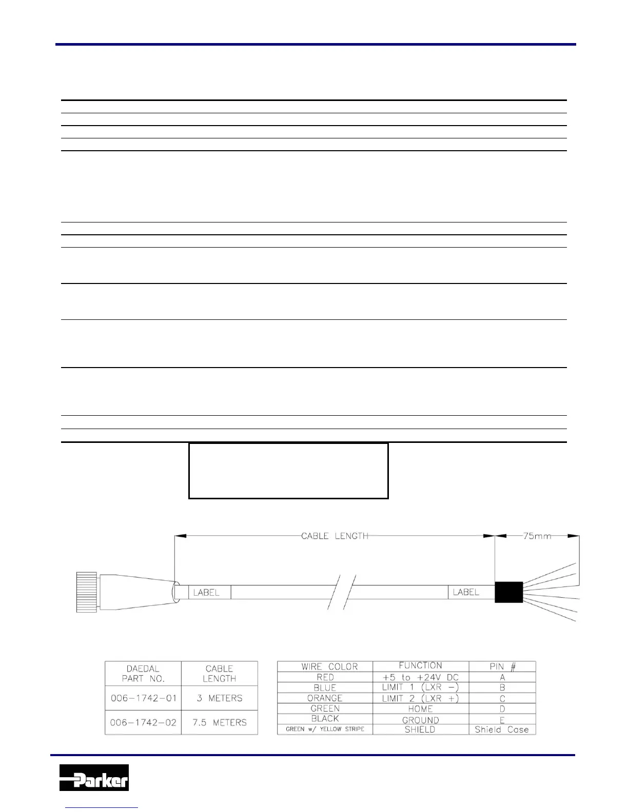
Sensor Pack Cable Wiring Diagram
NOTE: Limit 2 is the limit switch on the connector end of the sensor pack housing.
CAUTION: REVERSING SUPPLY
POTENTIAL WILL DESTROY SENSOR
Brown: +5 to +30VDC Supply
Blue: Ground Supply
www.comoso.com