404/406XR Series Product Manual Chapter 5 - Component Mounting Procedures
28
Parker Hannifin Corporation
1140 Sandy Hill Road
Irwin, PA 15642
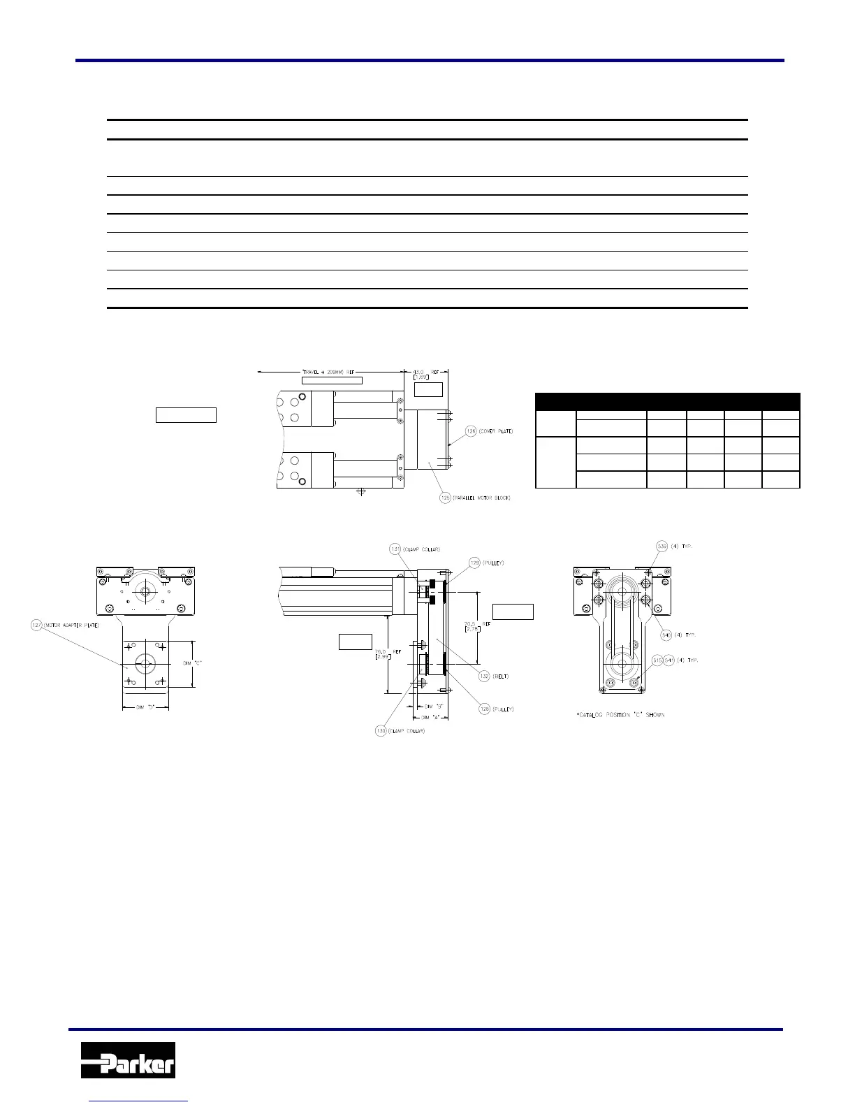
Locate correct parallel mounting hardware for bottom position ‘C’:
(4) M4 x 8 Button Head Screws
(4) M5 x 10 Socket Head Cap Screws
(4) M4 Ribbed Spring Washers
(4) M5 x 18 Socket Head Cap Screws
(4) M6 x 16 Socket Head Cap Screws
(4) M3 x 8 Button Head Screws
(4) M4 x 10 Button Head Screws
Apply a few drops of Loctite #609 to screw shaft. Mount Pulley #1 to positioner drive screw shaft by slipping it
over the screw shaft and up against the bearing assembly locknut. Tighten clamp screw to 13 in-lbs. Place
Shroud over pulley and onto mounting surface. Measure the distance from open face of shroud to the face of
pulley flange. The pulley should be recessed some distance from the open face of the shroud. Using depth
micrometer record this number.
Mount parallel mounting shroud (less cover plate) to 404/406XR series linear positioner in desired orientation.
Apply a few drops of Loctite # 242 on the screw threads. For side positions ‘A’ and ‘B’ install and tighten (2)
socket head cap screws, Item # 540, through the deep counterbored holes and install and tighten (2) button
head screws, Item # 517, through the remaining holes. For bottom position ‘C’ install and tighten (4) socket
head cap screws, Item # 540, 517, through the deep counterbored holes.
APEX 602/604
NEOMETRIC 70
www.comoso.com