Bulletin TI-FID1000C FID 1000 and 2500 Gas Stations
Parker Hannifin Corporation
Filtration and Separation Division
Haverhill, MA • 1-800-343-4048
www.parker.com/ags
6
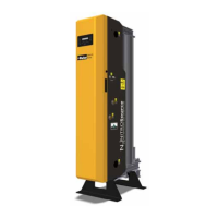
Compressed air - The Parker Balston FID 1000 and FID 2500 Zero Air Generators require a
source of clean compressed air for optimal operation. The compressed air should be as close
to instrument quality as possible, and supplied at a pressure and flow rate above that required
at the point of use. The temperature and/or dewpoint of the supply air should be at room
temperature (or lower), and it should be relatively free from compressor oil, hydrocarbons,
and particulate matter. Contamination of the catalyst bed may occur if it is exposed to certain
compounds (see warning below). If the compressed air supply has excess water, oil, or
particulate contamination, install extra prefiltration upstream from the unit (see Recommended
Accessories, page 18).
Chlorinated hydrocarbon compounds and chlorofluorocarbons (or freons) will perma
-
nently contaminate the hydrocarbon catalyst module in the FID ZAG generator. Ex-
treme care should be taken when specifying an air supply for the generator to ensure
that these compounds are not present in the air supply nor likely to get into the com-
pressor providing air to the generator.
The hydrocarbon catalyst module can also be contaminated by high concentrations
of lead, sulfur, or phosphorous compounds, heavy metals, and long chain polymers.
Care should be taken to avoid introducing these compounds into the Parker Balston
FID Gas Station. None of these compounds are to be stored near the inlet to the
compressor supplying the system with compressed air. The intake for the compressor
should be vented to the outdoors.
Connect the compressed air supply to the 1/4" NPT (female) inlet port in the top center of the
generator, back of instrument (see Figure 10).
Piping Components, FID 1000 and FID 2500 / ZAG - The inlet port for the Parker Balston
FID 1000 and FID 2500 Zero Air Generator is a 1/4" NPT (female) and is located at the top
center of the rear panel. Inlet tubing and fittings should be clean and rated for 125 psig
(8.5 Barg), minimally. The tubing and fittings used downstream from the FID 1000 and FID
2500 should be clean stainless steel or pre-cleaned refrigeration-grade copper (1/4" od x
.030" wall) and rated for 125 psig (8.5 Barg).
Do not use plastic tubing downstream from the generator. Outgassing from the plastic
may contaminate the zero-grade gas. Use PTFE tape on all inlet and outlet NPT fittings.
(Thread sealing compounds may contaminate the process stream).
Note: The use of plastic piping components or unclean copper or stainless steel piping com-
ponents will result in the FID Gas Station failing to meet zero air purity specifications.
Connect downstream delivery lines (Zero Air Outlet) to the 1/8" compression union port on the
middle of the generator.
Piping Components, FID 1000 and FID 2500 / Hydrogen - The outlet connection for the FID
1000 and FID 2500 / Hydrogen is a 1/8" compression fitting. All tubing and fittings down-
stream from the hydrogen generator should be clean stainless steel to minimize contamina-
tion of the hydrogen stream. If copper tubing has been used with hydrogen in the past and
has yielded acceptable results, there is no need to alter an existing piping configuration to
install the hydrogen generator.
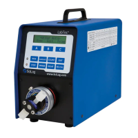
Flow Controller - A flow control device should be installed downstream from the zero air
outlet if one is not integral to the instrumentation used (P/N Model W-FM7583). If the flow
capacity of the generator is exceeded, the FID 1000 and FID 2500 / ZAG will fail to meet its
hydrocarbon specification (0.1 ppm for FID 1000, or 0.05 ppm for FID 2500).
Pressure Regulator - The FID 1000 and FID 2500 / Hydrogen pressure is preset to 66 psig
internally. In order to optionally regulate the output pressure, the customer needs to install a
pressure regulator down stream from the unit. The output pressure can be monitored using
the front panel digital display. There is an internal Pressure Relief Valve that is preset to
150 psig (10 Barg) in case of excess internal pressure build up. The expelled gas is chan-
neled through the pressure relief port, hydrogen vent, located in the back of the unit.
 Loading...