Bulletin TI-FID1000C FID 1000 and 2500 Gas Stations
Parker Hannifin Corporation
Filtration and Separation Division
Haverhill, MA • 1-800-343-4048
www.parker.com/ags
8
Installation and Operation
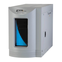
Figure 10 - Rear View of Unit
Water Reservoir
Start Up
The FID Gas Station is equipped with both an Automatic Fill and a Manual Fill Water design.
After carefully following all the preparation procedures in the Installation section, proceed as
follows:
For Autofill operation, the FID Gas Station incorporates a detection device which automati-
cally activates a Water Fill Solenoid when the water level is at the REFILL or EMPTY Level. In
order to function correctly, the FID gas station must be connected directly to a DIO Water sup-
ply. The FID Gas Station/H
2
must be supplied with deionized water with a resistivity of at least
5 Meg – Ohm /cm or greater. Both a Gravity Feed and a Pressure Feed Tubing assembly
can be located in the Accessories bag (P/N B02-0318). Select the required tubing, depending
on the DIO source, and attach to the Water Fill Port at the back of the FID Gas Station (see
Fig 10).
When the DIO set up is ready, turn the Power Switch to On. This automatically opens the
internal DIO Solenoid valve and the Resin Bed Reservoir/Water Reservoir will start to fill. The
device will continue to fill until the Water level reaches the REFILL mark. This triggers the
internal solenoid valve to close and the DIO demand will cease. Do not disconnect the DIO
water source if continuous FID/H
2
operation is desired.
Note: The H
2
generator will automatically shutdown if the water level becomes too low
and LOW WATER is displayed on the Digital screen.
Autofill
 Loading...