EasyManua.ls Logo

Parker Balston FID 1000 User Manual

Parker Balston FID 1000
21 pages
To Next Page IconTo Next Page
Page #1 background imageLoading...
Page #1 background image
Bulletin TI-FID1000C FID 1000 and 2500 Gas Stations
Parker Hannifin Corporation
Filtration and Separation Division
Haverhill, MA 1-800-343-4048
www.parker.com/ags
1
0ARKER"ALSTON&)$AND
&)$'AS3TATIONS
)NSTALLATION/PERATIONAND-AINTENANCE-ANUAL
Parker Hannifin Corporation
Filtration and Separation Division
Haverhill, MA • 1-800-343-4048
www.parker.com/ags
Bulletin TI-FID1000C
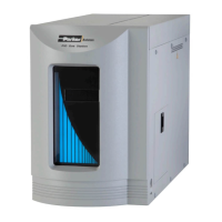
Figure 1 - FID Gas Stations
FID Gas Stations (see Figure 1) are completely engineered systems designed to
produce ultra pure, dry hydrogen gas from deionized water using a Proton Ex-
change Membrane cell. The hydrogen generator utilizes the principle of electrolytic
dissociation of water and hydrogen proton conduction through the membrane. The
hydrogen stream is dried using a coalescing filter,a drying tube and dessicant. The
outlet pressure of the hydrogen unit is 60 psi (4.08 Barg) with a maximum hydro-
gen delivery flow rate of 90 cc/min for Model 1000, and 250 cc/min for Model 2500.
The FID gas stations are ideal for use as fuel gas in Flame Ionization Detectors
(FID’s), Trace Hydrocarbon Analyzers, and other general laboratory equipment
requiring a source of pure hydrogen.
Parker Balston Gas Stations also incorporate a Zero Air Generator (ZAG) which will
replace inconvenient high pressure gas cylinders as a source of hydrocarbon-free
air. This will purify on site compressed air to a total hydrocarbon concentration of
less than 0.1 ppm (measured as methane). The ZAG may be used to generate fuel
for Flame Ionization Detectors (FID’s) or for a zero reference for any instruments
which measure hydrocarbon concentration. Model 1000 is capable of producing
1000 cc/min of zero grade air and will serve up to three FID’s, and Model 2500 will
serve up to six FIDs.
General Description
These instructions must be thoroughly read and understood before install-
ing and operating this product. Any modification of the product will void the
warranty. Failure to operate this product in accordance with the instructions
set forth in this manual and other safety governing bodies could jeopardize
the safety of the operator and void the safety certification of this product.
If you have any questions or concerns, please call the Technical Services
Department at 800-343-4048, 8AM to 5PM Eastern Time (North America only).
For other locations, please contact your local representative.
Do not use a Hydrogen gas storage vessel in conjunction with the Hydrogen
generator. Stored quantities of hydrogen pose an explosion hazard.
Normal precautions for any hydrogen supply should be taken when using
the hydrogen generator. DO NOT USE IN A SEALED OR UNVENTED ROOM.
CAUTION: DO NOT USE AN OPEN FLAME OR OTHER IGNITION SOURCE
WITHIN 10 INCHES (25cm) OF THE OXYGEN VENT!
4ECHNICAL
)NFORMATION
®
FRONT VIEW
RIGHT SIDE VIEW
Question and Answer IconNeed help?

Do you have a question about the Parker Balston FID 1000 and is the answer not in the manual?

Parker Balston FID 1000 Specifications

General IconGeneral
ManufacturerParker Balston
ModelFID-1000
Gas TypeHydrogen, Air
TypeFlame Ionization Detector (FID)
Power Requirements115 VAC, 60 Hz or 220 VAC, 50 Hz
Dimensions22 in. H x 14 in. W x 18 in. D (55.9 cm x 35.6 cm x 45.7 cm)
Weight65 lb (29.5 kg)
Flow RateUp to 1 L/min for each gas
Outlet PressureAdjustable, up to 60 psig (4.1 bar)
Inlet Pressure80-100 psig (5.5 - 6.9 bar)
PurityHydrogen: <1 ppm total hydrocarbons; Zero Air: <1 ppm total hydrocarbons, <1 ppm CO, <25 ppm moisture; Makeup Gas: Determined by source gas purity

Summary

General Description of FID Gas Stations

Zero Air System Overview

Hydrogen System Components

Installation and Operation Guidelines

General Installation Precautions

Install indoors, protect from severe weather, dust, and dirt. Unit is free-standing.

Pre-Operation Preparation Steps

Remove protective tape from ports and prepare the desiccant cartridge.

Utilities Setup and Connection

Power Supply Voltage Selection

Set the voltage selector to match the local power supply for optimal performance.

Deionized Water Supply Requirements

Use deionized water with a resistivity of at least 5 Meg-Ohm/cm.

Compressed Air Supply and Piping

Compressed Air Quality Standards

Requires clean air, free from oil, hydrocarbons, and particulates. Avoid chlorinated compounds.

Quick Start Procedures

Startup Procedures and Settings

Initial Startup Steps

Connect power, supply compressed air, turn on unit, and check display.

Operation Guidelines and Monitoring

Continuous Operation Best Practices

Designed for 24/7 operation; monitor hydrogen flow and water level.

Hydrogen Cell Integrity Maintenance

Maintain water level, minimize piping dead-volume, avoid freezing and sudden demand.

System Diagnostics and Faults

Built-in monitoring alerts operator to faults with visual and audible alarms.

Troubleshooting Common Issues

Troubleshooting: Hydrogen Overflow

Check for leaks, demand exceeding capacity, or install flow control.

Troubleshooting: Low Output Pressure

Check demand, piping, external leaks, or install flow control.

Troubleshooting: No Hydrogen Delivered

Check power, water level, shutoff valve, and for piping leaks.

Troubleshooting: Excess Hydrocarbons

Ensure adequate startup temperature and check zero air flow demand.

Routine Maintenance Procedures

Catalyst Assembly Module Replacement

Replace the catalyst module every 2 years for optimal performance.

System Specifications

Related product manuals