16
Parker Hannifin Corporation
Proportional DC Valves
Series D*FC, D*1FC
Operation Manual
D_FC 5715-686 UK 07.02.2019
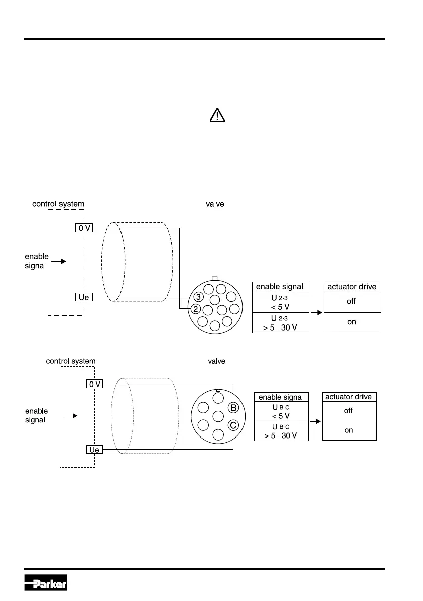
Wiring diagram of enable input code 7 (6 + PE)
A signal voltage enables the actuator drive of the
valve. Continuous operation of the valve requires a
permanent voltage 5...30 V (i.e. the supply voltage).
In case of disabling the signal the valve will reach its
hydraulic default (power down) position in no time
independently from the command signal value. At
the same time the position controller output will be
clamped. In case of restarting the enable signal,
the valve spool takes its position always out of the
power down. Preferable the enable signal should
be switched on together with the hydraulic pressure
supply. This forces the actuator drive into drop out
condition when the hydraulic system is switched off,
and it avoids needless heating of the actuator.
The enable function represents no safety
arrangement against unwanted valve opera-
tion in terms of rules for accident prevention!
To block the valve function under all conditions,
more advanced steps are necessary, i.e.
the installation of additional safety check
valves.
Enable input (only for Code 5 / 11+PE and
Code 7 / 6 + PE)
Wiring diagram of enable input Code 5 (11 + PE)

 Loading...