4
Parker Hannifin Corporation
Proportional DC Valves
Series D*FC, D*1FC
Operation Manual
D_FC 5715-686 UK 07.02.2019
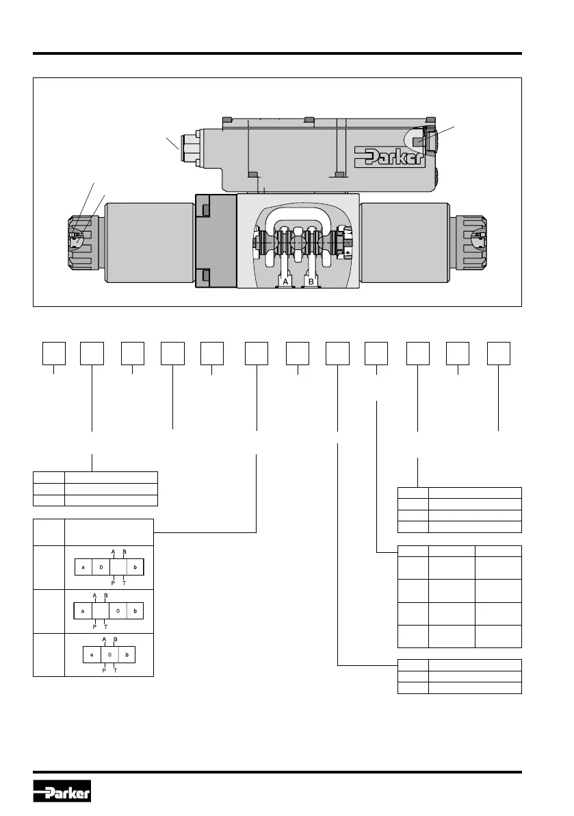
Ordering code D*FC
1. Introduction
D*FC
Main connector
(always on A-side
of main stage)
Parametrizing
connection
Manual override
Air bleeding
Nominal
size
DC
valve
Command
signal
Seal Design
series
(not required
for ordering)
Proportional
control
Electrical
options
D F C 9 3
Spool/
body
design
Spool
type
(see
catalogue)
Spool
position
1)
High
dynamics
Drain port Y
plugged
4)
Code Nominal size
1 NG06 / CETOP 03
3 NG10 / CETOP 05
Code Seal
N NBR
V FPM
Code Signal Function
B 0...±10 V
0...+10 V
P -> A
E
0...±20
mA
0...+20 mA
P -> A
K 0...±10 V
0...+10 V
P -> B
S 4...20 mA
12...20 mA
P -> A
Code
Spool position on
power down
A
2)
B
2)
C
3)
1)
On power down the spool moves in a defined position.
This cannot be guaranteed in case of single flow path on the control edge A – T resp.
B – T with pressure drops above 120 bar or contamination in the hydraulic fluid.
2)
Approx. 10 % opening, only zero lapped spools and underlap spools.
3)
Only for overlapped spools.
4)
Needs to be removed at tank pressure >35 bar.
5)
Please order connector separately.
Code Electronic options
5)
0 6 + PE
5 11 + PE
7 6 + PE with enable

 Loading...