5
Parker Hannifin
Pump and Motor Division
Trollhättan, Sweden
Service Manual
Series F11
Bulletin HY30-5503-M1/UK
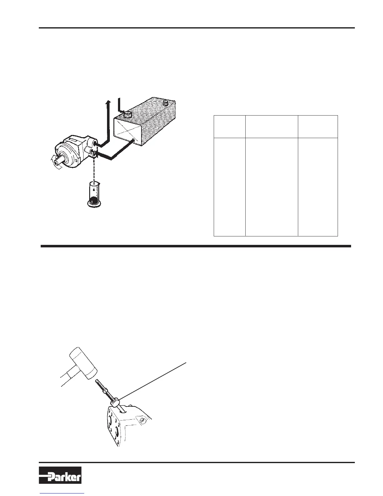
Operational Check
The general condition of the unit can be established by
checking the drain flow. Remove the drain line and keep the
drain port above a suitable container. Run the unit at normal
speed and pressurize the system to 150 - 200 bar .
Measure the drain flow for one minute; if it exceeds the
maximum figures shown below, the unit is worn or damaged
internally and should be replaced or repaired. Also, check
for leakage at the shaft seal and between the bearing and
barrel housings.
Drain Flow
Repair
Tools and Supplies
Metric Allen keys, retaining ring spanners, and a torque
wrench with suitable metric sockets are required for the
disassembly and assembly of the F11 series, plus common
hand tools.
Series Normal Max.
(l/m) (l/m)
F11-5 0.2 1.0
F11-10 0.3 1.5
F11-19 0.4 2.0
F11-28 0.4 2.0
F11-39 0.5 2.5
F11-58 0.7 2.7
F11-78 1.0 3.0
F11-110 1.0 3.0
F11-150 1.2 3.0
F11-250 1.5 3.0
Special tool for F11-250 no
longer available.
See SI 09/03
 Loading...