8
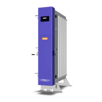
2.3 Overview of the equipment
Please refer to diagram A3 in Annex A.
Key:
1
N
2
Outlet port to buffer (G1”) *
2 Cable Glands
Pre-treatment dryer power supply
cable gland. (Rating: 115V 1A /
230V 0.5A)
External start / stop circuit cable
gland.
Pre-treatment dryer purge economy
cable gland.
Remote alarm circuit cable gland.
Mains supply cable gland
3 Pressure Gauges
Column A pressure gauge
Column B pressure gauge
N
2
Outlet pressure gauge
Air inlet pressure gauge
4
N
2
inlet port from buffer vessel
(G1/2”) *
* Connection available on both sides of the generator.
5
N
2
Outlet port (G1/2”) *
6 Air Inlet port (G1”) *
7 User control interface with 20 x 2 line menu display.
8 Access door
9Facia
10 4 – 20mA cable gland
11
O
2
Analyser calibration port

 Loading...