Enable input and status output
The enable input activates (9...30 VDC) the power
amplifiers or deactivates them (0 VDC). The status
output delivers 18...30 VDC during normal operation.
It switches to 0 VDC in case of an error.
Valve Solenoid
Nominal Current Dither
I
max
A-side (IA) I
max
B-side (IB) Amplitude (P5) Frequency (P6)
TDA
L 1.3 A (4) a. P3=80.7 1.3 A (4) 1.6 21
M 2.7 A (2) 2.7 A (2) 0.8 21
DSA L 1.3 A (4) 1.3 A (4) 1.6 88
VBY/VMY
L 0.8 A (0) 0.8 A (0) 2.4 88
M 2.7 A (2) 2.7 A (2) 2.4 88
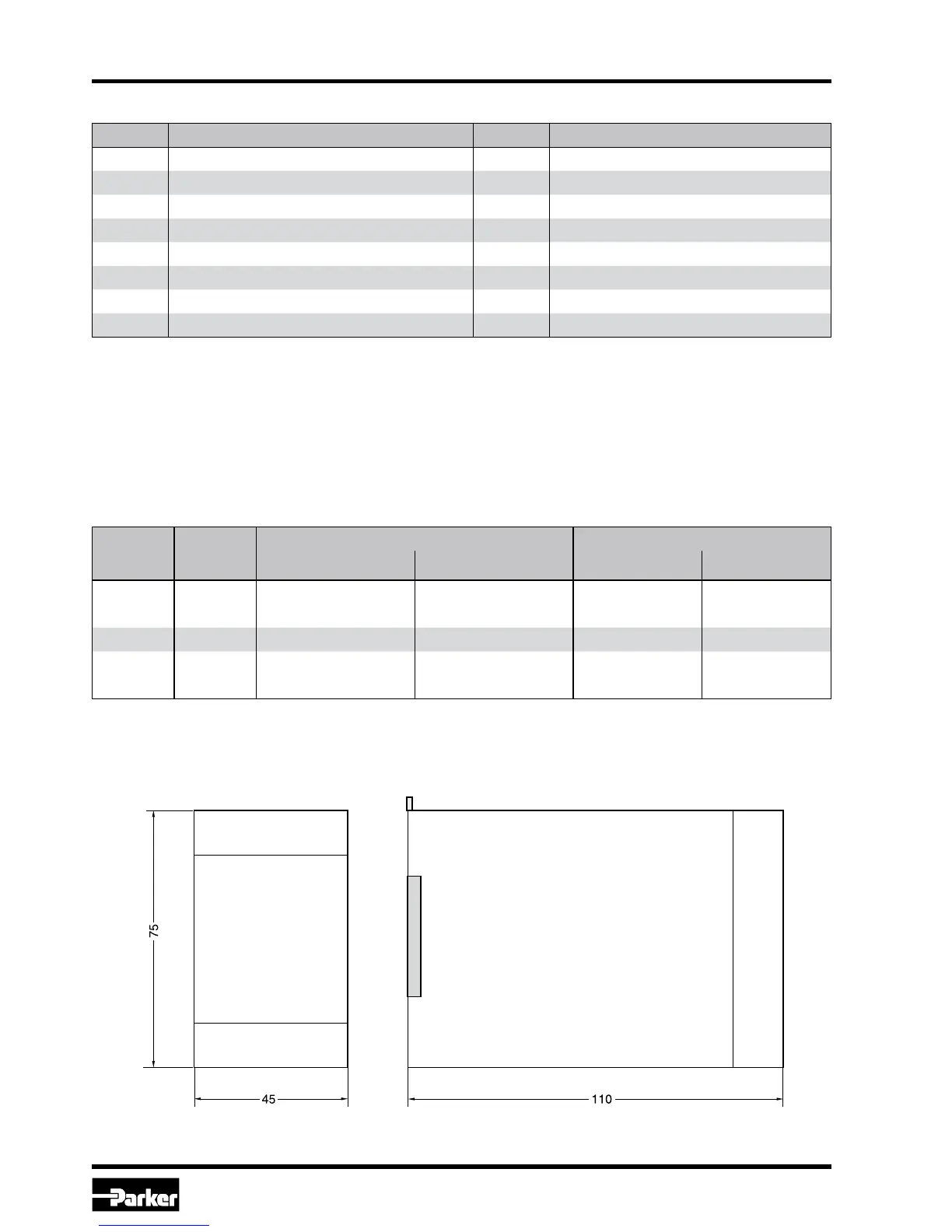
Dimensions
Pin Description Pin Description
1 + supply 18...30 VDC 9 channel A
2 GND supply 0 VDC 10 channel A
3 Enable input 9...30 VDC 11 channel B
4 Status output 0 VDC / 18...30 VDC 12 channel B
5 Cmd. A-channel 0...+10 VDC 13 int. command 1 0 VDC / 18...30 VDC
6 Cmd. B-channel 0...+10 VDC1 4 int. command 2 0 VDC / 18...30 VDC
7 GND cmds./dig.IO 0 VDC 15 int. command 3 0 VDC / 18...30 VDC
8 PE Earth 16 int. command 4 0 VDC / 18...30 VDC
Pinning
Please obey supply voltage (see technical data sheets).
Standard Parameters