Parameter Range
Default
value
Unit Function
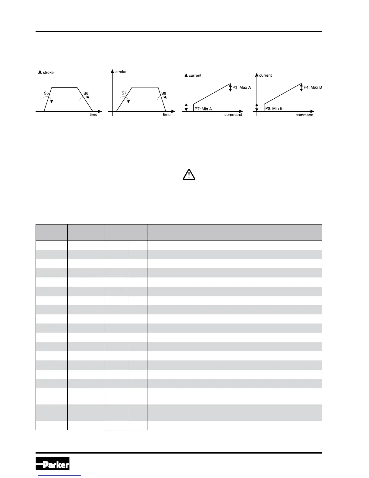
P3 50.0...100.0 100.0 % max. current A-channel
P4 50.0...100.0 100.0 % max. current B-channel
P5 0.0...10.0 0.0 % Dither amplitude A-channel
P6 0...300 0 Hz Dither frequency A-channel
P7 0.0...50.0 0.0 % Min. current A-channel
P8 0.0...50.0 0.0 % Min. current B-channel
Q5 0.0...10.0 0.0 % Dither amplitude B-channel
Q6 0...300 0 Hz Dither frequency B-channel
S1 0.0...+100.0 0.0 % Internal command 1
S2 0.0...+100.0 0.0 % Internal command 2
S3 0.0...+100.0 0.0 % Internal command 3
S4 0.0...+100.0 0.0 % Internal command 4
S5 0...32500 0 ms Ramp UP A-channel
S6 0...32500 0 ms Ramp DOWN A-channel
S7 0...32500 0 ms Ramp UP B-channel
S8 0...32500 0 ms Ramp DOWN B-channel
IA 0, 1, 2, 3, 4 – –
Nominal current A-channel, 0=0.8 A; 1=3.5 A; 2=2.7 A; 3=1.8 A;
4=1.3A
IB 0, 1, 2, 3, 4 – –
Nominal current B-channel, 0=0.8 A; 1=3.5 A; 2=2.7 A; 3=1.8 A;
4=1.3 A
n 1, 2 2 – Allocation of internal command signals
All parameters are saved in an EEPROM and become active directly after supply voltage is switched on.
Ramp-function / Min-Max-function
The PCD00A-400-electronic includes two internal
programmable ramps for each channel. Addition-
ally a current step may be programmed (Min) and
/ or the current may be limited (Max) for each
Nominal current adjustment
The nominal current can be adjusted by one pa-
rameter separately for each channel (Pin 9, 10,
or 11, 12). The default nominal current is 800 mA.
Parameterization
All parameters can be adjusted via a serial con-
nection (RS232C-null modem) by the computer-
software.
The computer-software shows the parameters in
textform. So they are easy to use.
The connected valves may not operated
before loading an appropriate parameter set
from the PC into the module electronics.
Example of parameter chart