Do you have a question about the Parker SLVD1N and is the answer not in the manual?
Explanation of danger, warning, and caution symbols used in the manual.
High voltage risks, grounding, cabinet requirements, and component compliance.
High voltage, live parts, leakage current, and hot surface warnings.
Warnings about removing covers, warranty voiding, and drives not being field repairable.
Details power supply requirements for the control and power stages.
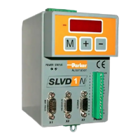
Identifies and describes the layout of various connectors (X1-X7).
Specifies fuse sizing and recommendations for overload and short-circuit protection.
Guidelines for grounding bar dimensions and connection methods.
Explains EMC ground and safety ground systems for interference reduction.
Details shielding connection methods for reducing interference.
Details procedure for operating the drive at reduced voltage for safety.
Explains operation with standard AC or continuous DC voltage supplies.
Steps to restore the converter to its factory default parameter settings.
How to select between synchronous and asynchronous motor types.
Procedure for updating motor parameters after initial setup or data save.
Explains how to configure the speed and current loop feedback sensor type.
Details encoder phasing procedures.
Procedure for encoder phasing using a specific command and status checks.
Procedure for encoder phasing involving motor vibration and status checks.
Configuration for SinCos encoders using the EnDat interface, including initialization.
Step-by-step guide for initial setup and connection of motor and references.
Explains how to estimate the Pr16 parameter for system gain based on motor data.
Provides formulas and steps for parameter adjustment without an oscilloscope.
Details decimal parameters (Pr0-Pr220) with their descriptions, fields, ranges, and defaults.
Explains binary parameters (Pb40-b231.15) related to system status, configuration, and control.
Information on storing and using trapezoidal profiles in memory for mode 13.
Details trapezoidal profile generation parameters for electronic cams.
Configures speed, acceleration, and deceleration ramps for speed mode.
Explains the four available cam tables (TAB0-TAB3) and their functions.
Provides axis reset procedures using homing sensors and predefined bits.
Details the MotionWiz software for drive configuration and system control via PC.
Steps to install and use the MotionWiz software for drive programming.
Details CANopen DSP402 compliance, transmission speeds, and PDO mapping.
Defines the bits and structure of the Controlword for device state and mode control.
Details the Statusword bits indicating drive state, mode, and manufacturer-specific options.
| Brand | Parker |
|---|---|
| Model | SLVD1N |
| Category | Power Tool |
| Language | English |