Do you have a question about the Parker SLVD7N and is the answer not in the manual?
Explains the meaning of safety symbols and signals used in the manual.
Provides general safety information and user qualifications for operating the equipment.
Outlines safety procedures and precautions for installing and commissioning the drive.
Provides critical safety guidelines for operating the drive, including high voltage and hot surface warnings.
Details safety warnings related to equipment maintenance and warranty voiding.
Specifies power supply requirements for the control and power stages of the drive.
Provides detailed technical specifications, including input/output characteristics and braking.
Provides instructions for vertical mounting and required clearance space.
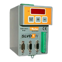
Illustrates the layout of signal connectors and provides terminal block details.
Provides instructions for reducing conducted and radiated interference using grounding, shielding, and filtering.
Explains how to adjust the speed control loop for optimal performance.
Explains how to select and configure different operating modes for the drive.
Details the setup for torque control, including necessary parameter settings.
Explains operating mode 13, combining Digital Lock and dynamic positioner functions.
Describes operating mode 14 for electronic cam functions, essential for packaging machines.
Details operating mode 11, which supports two electronic cams.
Details the CANopen DSP402 implementation, including node settings and transmission speed.
Explains the homing mode (operative mode 200) for seeking the home position.
Details the profile position mode for executing target positions with motion profiles.
Details the interpolated position mode for regulating position based on cycle time.
Details the Cyclic Synchronous Position mode for controlling position, velocity, and torque.
| Brand | Parker |
|---|---|
| Model | SLVD7N |
| Category | Power Tool |
| Language | English |