Do you have a question about the Parker SLVD5N and is the answer not in the manual?
Outlines safety precautions for transporting and storing the drive unit.
Details safety requirements and procedures for commissioning the drive.
Specifies safety procedures and warnings for operating the drive.
Provides safety warnings and guidelines related to the maintenance of the drive.
Details the power supply requirements for the control and power stages of the drive.
Provides detailed technical specifications for various drive models.
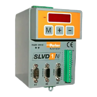
Illustrates the layout of the signal connectors on the SLVD-N drive.
Illustrates various diagrams for connecting the drive to the power supply.
Shows connection diagrams for connecting the motor to the drive.
Describes the procedure for using the drive in low voltage mode for safety.
Explains how to operate the converter in high voltage mode.
Explains how to configure the type of sensor used for speed and current control.
Explains the procedure for encoder phasing, including type 1 and type 2 methods.
Provides a step-by-step guide for the initial commissioning of the converter.
Details the process of adjusting the speed control parameters for optimal performance.
Lists and explains decimal parameters for drive configuration.
Lists and explains binary parameters used for drive control.
Describes the different operating modes available for the drive.
Explains the torque control function within operating mode 1.
Details operating mode 13 for Digital Lock and Positioner functions.
Explains operating mode 14 for electronic cam functions.
Describes operating mode 11 for electronic cam functions.
Describes the internal pico-PLC for connecting external world to parameters.
Details the serial communication protocol used by the drive.
Describes the CANopen DSP402 interface implementation for EtherCAT.
Provides a summary of the DSP402 dictionary objects in the SLVD-N.
Details Object 6040h, the Controlword, used for device control.
| Brand | Parker |
|---|---|
| Model | SLVD5N |
| Category | Power Tool |
| Language | English |