English
2 / 6
SPS010/0250 (60Hz)
2 Introduction
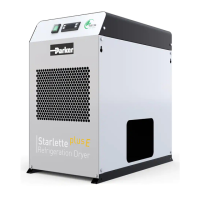
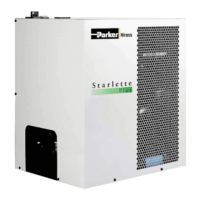
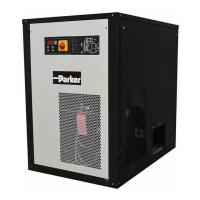
This manual refers to refrigeration dryers designed to guarantee high
quality in the treatment of compressed air.
2.1 Transport
The packed unit must:
• remain upright;
• be protected against atmospheric agents;
• be protected against impacts.
2.2 Handling
Use a fork-lift truck suitable for the weight to be lifted, avoiding any type
of impact.
2.3 Inspection
a) All the units are assembled, wired, charged with refrigerant and oil
and tested under standard operating conditions in the factory;
b) on receiving the machine check its condition: immediately notify the
transport company in case of any damage;
c) unpack the unit as close as possible to the place of installation.
2.4 Storage
If several units have to stacked, follow the notes given on the packing.
Keep the unit packed in a clean place protected from damp and bad
weather.
3 Installation
3.1 Procedures
Install the dryer inside, in a clean area protected from direct atmospheric
agents (including sunlight).
Y Comply with the instructions given in par. 8.2 and 8.3.
All dryers must be tted with adequate pre- ltration near the dryer air
inlet. Seller is excluded any obligation of compensation or refund for any
direct or indirect damage caused by its absence
Y Pre- lter element (for 3 micron ltration or better) must be replaced
at least once a year, or sooner as per manufacturer recommendations.
Y Do not invert the compressed air inlet and outlet connections.
3.2 Operating space
Y Leave a space of 1.0 m around the unit.
Floor installation Wall mounted
1 m
1 m
1 m
1 m
1 m 1 m
1 m
1 m
1 m
1 m
1 m 1 m
1 m
3.3 Tips
To prevent damage to the internal parts of the dryer and air compres-
sor, avoid installations where the surrounding air contains solid and/or
gaseous pollutants (e.g. sulphur, ammonia, chlorine and installations in
marine environments).
The ducting of extracted air is not recommended for versions with axial
fans.
3.4 Electrical connection
Use approved cable in conformity with the local laws and regulations (for
minimum cable section, see par. 8.3).
Install a differential thermal magnetic circuit breaker with contact open-
ing distance 3 mm ahead of the system (RCCB - IDn = 0.3A) (see the
relevant current local regulations).
The nominal current In of the magnetic circuit breaker must be equal to
the FLA with an intervention curve type D.
3.5 Condensate drain connection
If a timed or electronic unloader is installed, use terminals CN (R1-S1)”
(see par. 8.8).
For timed and electronic drains: refer to separate manual supplied with
the dryer for speci c details concerning the condensate drain.
Y Make the connection to the draining system, avoiding connection in
a closed circuit shared by other pressurized discharge lines. Check the
correct ow of condensate discharges. Dispose of all the condensate in
conformity with current local environmental regulations.
4 Commissioning
4.1 Preliminary checks
Before commissioning the dryer, make sure:
• installation was carried out according that given in the section 3;
• the air inlet valves are closed and that there is no air ow through the
dryer;
• the power supply is correct.
4.2 Starting
QS
a) Start the dryer before the air compressor by means of the main power
switch “QS”, the display shows “DRY”
;
b) after at least 5 minutes slowly open the air inlet valve and subse-
quently open the air outlet valve: the dryer is now performing its air dry-
ing function.
4.3 Operation
a) Leave the dryer on during the entire period the air compressor is
working;
b) the dryer operates in automatic mode, therefore eld settings are not
required;
c) in the event of unforeseen excess air ows, by-pass to avoid over-
loading the dryer.
4.4 Stop
a) Stop the dryer 2 minutes after the air compressor stops or in any case
after interruption of the air ow;
b) do not allow compressed air to ow through the dryer when the latter
is not running;
c) switch off at the main power switch «QS». The power light goes out
and the compressor stops.