Parker Hannifin Corporation
Instrumentation Valve Division
Jacksonville, Alabama
MI-104
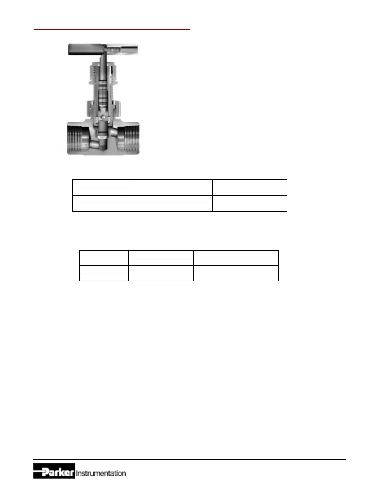
Figure 1: U Series Needle Valve
Cross Sectional View
Table III: Lock Nut
Hex Wrench Sizes and Tightening Requirements
Valve Size Hex Wrench Size Torque Requirement
U6 model 3/4 inch 125 in-lbs (14.1 N-m)
U12 model 15/16 inch 150 in-lbs (16.8 N-m)
U16 model 1 1/4 inch 150 in-lbs (16.8 N-m)
Table IV: Bonnet Nut
Hex Wrench Sizes and Tightening Requirements
Valve Size Hex Wrench Torque Requirements
U6 model 15/16 inch 65 ft-lbs. (88 N-m)
U12 model 1-1/4 inch 75 ft-lbs. (101 N-m)
U16 model 1-1/2 inch 100 ft-lbs. (135 N-m)
PANEL MOUNTED VALVES
The panel must have a through-hole diameter of correct diameter. The maximum panel thickness is 1/4 inch (6.4
mm).
U6 model 41/64 inch (16.2 mm)
U12 model 53/64 inch (21.0 mm)
U16 model 1-1/64 inch (25.8 mm)
1.Remove the Handle by unthreading the Set Screw in the side of the Handle with the following size allen wrench:
U6 model 3/32 inch
U12 model 3/32 inch
U16 model 1/8 inch
2.Grip the Packing Nut with a wrench as listed in Table II. With another wrench (as listed in Table III), loosen the
Lock Nut.
3.Remove both the Packing Nut and the Lock Nut by unthreading until completely removed.
4.Insert the Valve through the hole in the panel and assemble the Panel Nut onto the Bonnet finger-tight. For assembly,
grip the large Bonnet Nut with a hex wrench as listed in Table IV and tighten the Panel Nut securely.
CAUTION: Do not grip the Valve Body or loosen the Bonnet Nut.
5.Thread the Lock Nut onto the Bonnet. Thread the Packing Nut onto the Bonnet and tighten in accordance with
Table II.
6.Tighten the Lock Nut against the Packing Nut in accordance with Table III.
7.Re-install the Handle with the Set Screw onto the Stem.
2
 Loading...


