EN | Operating manual Installation
28 WVM 45 -1450
Installation of pipelines
To ensure proper operation of the dryer, its connection to the compressed air system must be
free from stress.
Prior to installation, check all incoming and outgoing compressed air lines and valves for
damage or contamination.
Inspect screw connections and retighten, if necessary (screw connections might become
loose during transport).
Ensure that the pipelines are not under any stress when installed!
Stress on pipes might result in the rupturing of the lines during operation, re-
sulting in damage to persons and property.
Connect the dryer to the compressed air system, while heeding rated diameter and
pressure.
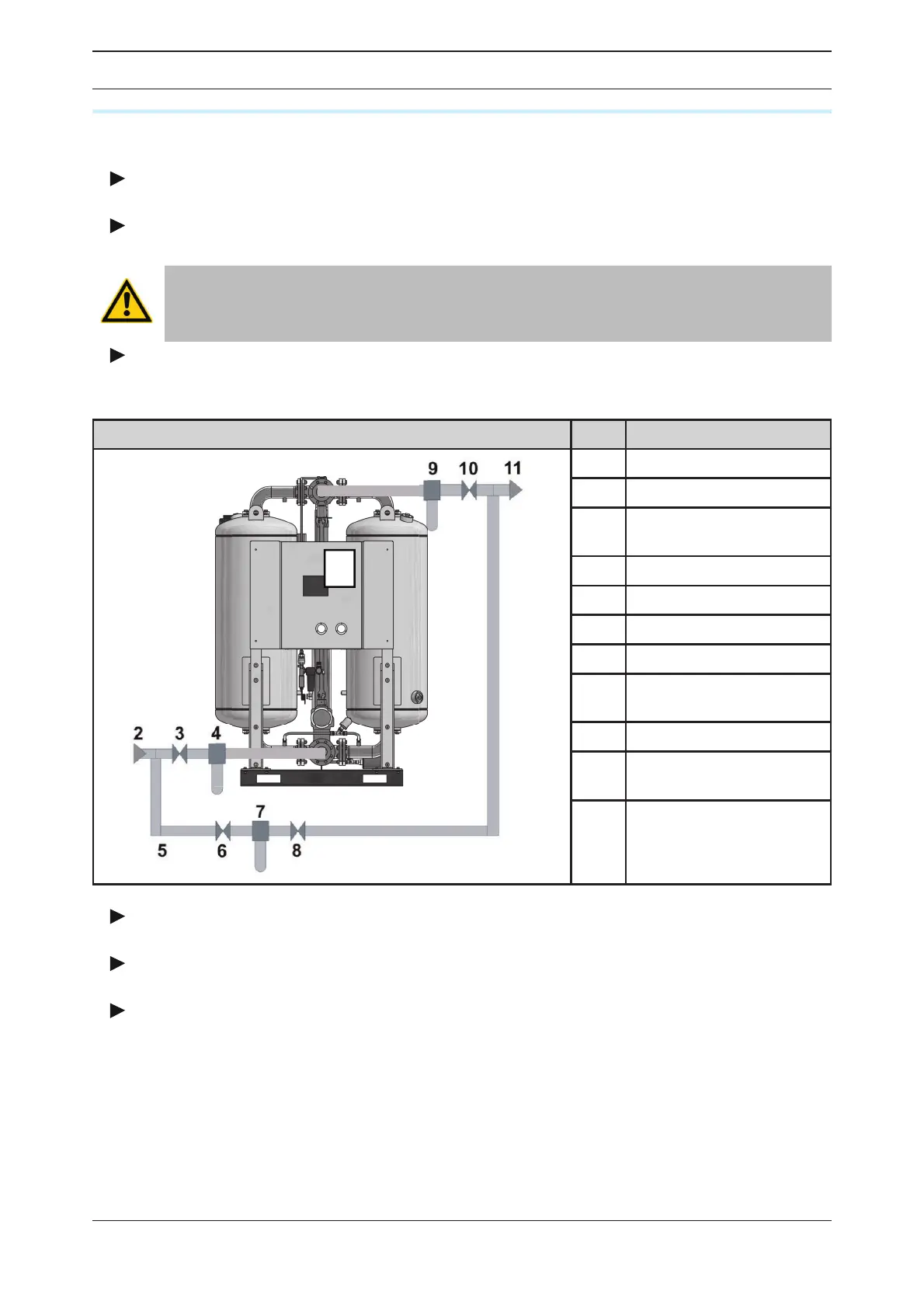
The gure below shows a proper installation.
Compressed air system Item Component
1
1 Dryer
2 Humid air inlet
3
Compressed air inlet
valve
4 Pre- lter
5 Bypass line
6 Valve in bypass line
7 Bypass lter
8
Valve at outlet of by-
pass lter
9 After lter
10
Compressed air outlet
valve
11 Dry air outlet
Example of a proper installation with bypass line
The connecting lines of the preliminary lter (4) should be at a slight slope towards the
lter.
A shut-off valve (3, 10) at both the inlet and outlet for the compressed air must be in-
stalled.
In units with bypass line (5) and additional shut-off valve:
Ensure that the line is installed in such a way that the compressed air ow must not be inter-
rupted during maintenance of the dryer.
 Loading...