Ref. No. Part Description Ref. No. Part Description
1―2 Optional cross wedge 40―43 Motor rear end plate assembly
3 Wedge 44 Motor shell
4 Dipstick 45 Stator
5 Tank 46 Rotator
6 Ram 47 Connecting box bottom assembly
7 Nylon liner 48―53 Key switch assembly
8 Motor frame 54―59 Capacitor assembly
9 Rear leg 60―62 Cable fastener assembly
10―13 Control rod assembly 63 Power cable and plug
14 Front leg 64 Rubber cover
15―16 Bolt assembly for draining oil 65―67 Connection box cover assembly
17 Valve encase 68―71 Motor front end plate assembly
18 Cylinder fixing knob 72―73 Fan assembly
19―21 Oil tube (valve-tank) 74―76 Fan cover assembly
22 Hydraulic valve 77―80 Towing handle assembly
23―25 Oil tube (pump-valve) 81―84 Long front frame assembly
26 Hydraulic cylinder 85―87 Main shield assembly
27―29 Cylinder-ram connecting assembly 88―90 Safe guard assembly
30―32 Hydraulic hose 91 Control handle
33 Oil filter 92―94 Wheel assembly
34―36 Oil tube (tank-pump) 95―98 Wheel frame assembly
37-39 Hydraulic pump assembly 99 Wheel axis
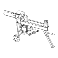
6. Electric circuit principle diagram
A. Power cable
B. Switch
C. Wiring board
D. Motor lead wire
E. Thermal protector
F. Main winding
G. Aux. winding
H. Capacitor
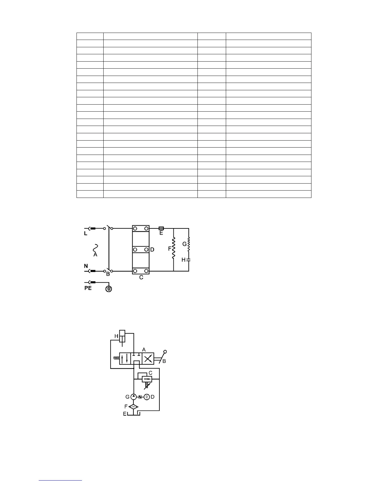
7. Hydraulic circuit principle diagram
A. Hydraulic valve
B. Control handle
C. Relief valve
D. Electric motor
E. Hydraulic tank
F. Oil filter
G. Hydraulic pump
H. Hydraulic cylinder
6
Note: The mains connection must have maximum 16A.