PWSA 20-Li F4
■ 12
│
GB
│
CY
♦ Turn the blade guard to the required position
(working position). Make sure that the blade
guard is positioned in such a way that the
blade guard fixture lies over one of the
5 bulges on the blade guard
(see Fig. E
(fold-out page).
♦ Ensure that the blade guard fixture is firmly
seated in the respective bulge
.
Fitting the additional handle
CAUTION!
► For safety reasons, this appliance may only
be used with the additional handle .
Failure to do so can lead to serious injury.
The additional handle can be screwed
onto the left, the right or the top, depending
on the job at hand.
Fitting/changing the roughing/
cutting disc
Always wear protective gloves when
changing cutting/rough grinding discs.
Pay attention to the dimensions of the roughing/
cutting disc. The diameter of the hole must fit the
attachment flange without any play. Do not use
a reducer or adapter.
NOTE
►
Use only discs which are free of dirt.
■ Use only grinding discs whose permissible
speed rating is at least as high as that on the
type plate on the power tool.
■ RISK OF INJURY! Press the spindle locking
button only when the attachment spindle
is at a complete standstill.
♦ Press the spindle locking button to lock the
motor.
♦ Undo the clamping nut using the two-hole
mounting spanner (see fig D).
♦ Place the rough grinding or cutting disc with the
label side towards the appliance on the attach-
ment flange .
♦ Then replace the clamping nut on the attach-
ment spindle with the raised side facing up.
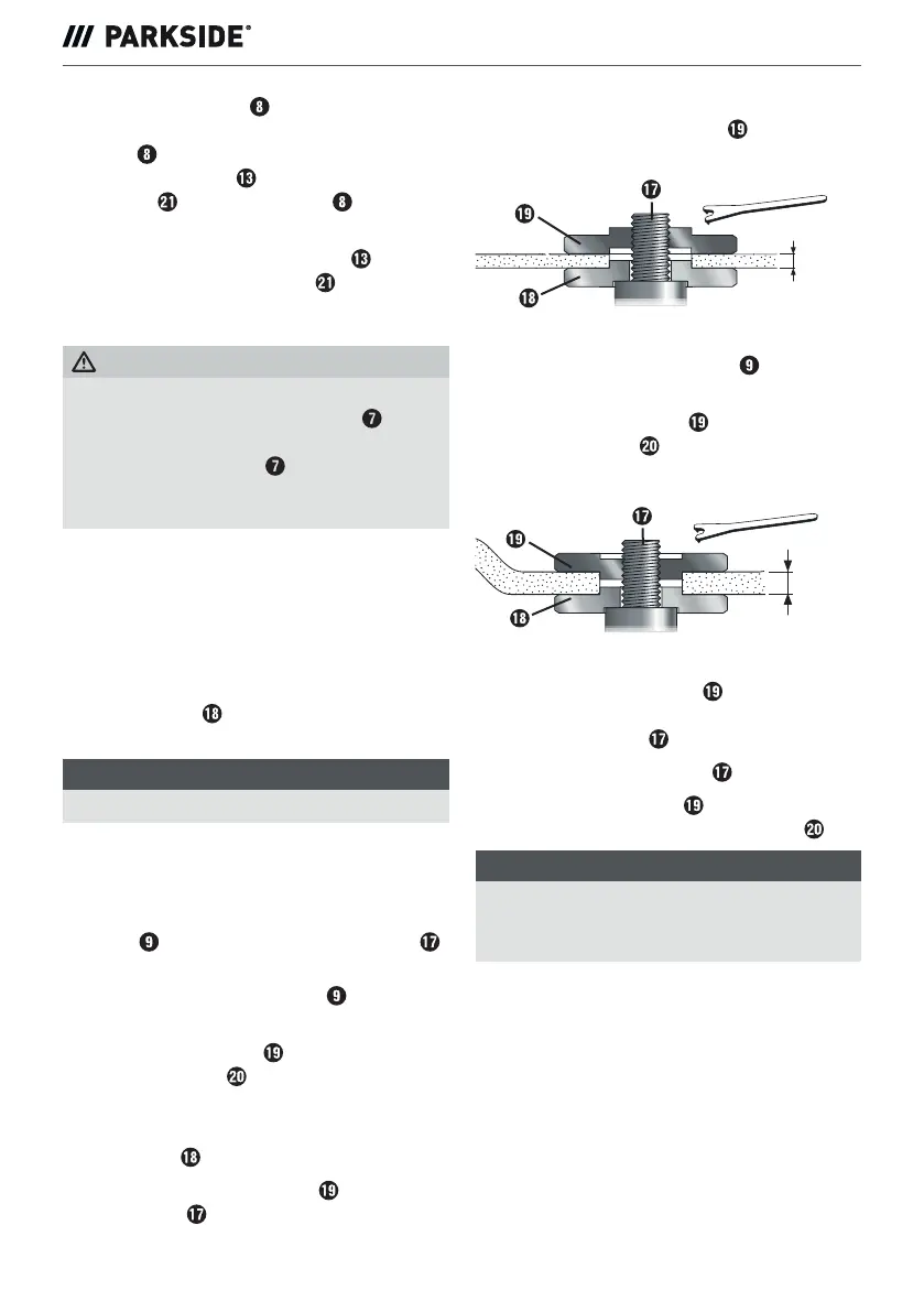
With thin grinding discs (see fig. 1)
♦ The collar of the clamping nut faces upwards
so that a thin grinding disc can be fitted safely.
≤ 3,2 mm
Fig. 1
♦ Press the spindle locking button to lock the
motor.
♦ Tighten the clamping nut using the two-hole
mounting spanner .
With thick grinding discs (see fig. 2)
> 3,2 mm
Fig. 2
The collar of the clamping nut
faces downwards
so that the grinding disk can be fitted securely onto
the attachment spindle .
♦ Lock the attachment spindle .
♦ Tighten the clamping nut in a clockwise direc-
tion using the two-hole mounting spanner .
NOTE
►
If the disc does not turn smoothly or vibrates
after the change, the disc must be replaced
immediately.
♦ For safety's sake, run the appliance at maximum
speed for 60 seconds after every disc change.
Be aware of unusual noises and sparks.
♦ Check whether all the fastening elements are
correctly fitted.
♦ Make sure that the arrow showing the direction
of rotation (if any) on the cutting or rough
grinding discs (including diamond cutting discs)
and the direction of rotation of the appliance
(arrow showing the direction of rotation on the
head) match.
 Loading...