Do you have a question about the Parr Instrument 4838 and is the answer not in the manual?
Lists other publications relevant to the instrument and its components.
Outlines the manual's coverage of installation and operation of the 4838 Reactor Controller.
Describes the typical use of the 4838 Reactor Controller with pressure vessels and reactors.
Explains the meaning of various symbols used in the manual and on the product.
Provides critical safety instructions to prevent electrical shock during operation.
Lists precautions to prevent personal injury, including handling hazardous materials.
Instructs on safe methods for moving the instrument.
Specifies the designed purpose of the controller and user responsibility.
Provides guidelines for cleaning and maintaining the controller.
Details electrical specs: voltage, current, frequency.
Lists recommended operating and storage environmental conditions.
Lists technical specs: input type, range, accuracy, control action.
Details parameters for the heater loop, including PID settings.
Emphasizes user's role in safe operation and equipment selection.
Guides selection of appropriate vessels and compliance with codes.
Highlights importance of user training and regular maintenance.
Provides instructions for unpacking and inspecting the equipment for damage.
Advises on placing the controller and ensuring proper ventilation and access.
Details labeled connections on the rear panel for various inputs and outputs.
Explains the use of the heating output connector with specific heater assemblies.
Describes connections for temperature and pressure sensors.
Identifies the connector used for communication output.
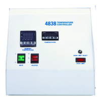
Describes the function of front panel switches and indicator lights.
Explains the operation of the three-position heater switch.
Describes the function of the high limit indicator and reset procedure.
Notes the location and importance of the main power switch for accessibility.
Details the instrument and load fuses and their protective role.
Explains the factory preset high temperature limit and its alarm indication.
Provides step-by-step instructions for opening the controller cabinet.
Describes the safety feature that shuts off power if the thermocouple circuit fails.
Explains how the high limit control trips and requires manual reset.
Lists field-serviceable fuses with their ratings and part numbers.
Introduces the microprocessor-based control module and its PID capabilities.
Explains setpoint control for adjusting temperature to a desired value.
Details the steps to adjust the temperature setpoint using the controller interface.
Describes how to adjust the high temperature alarm setpoint to prevent overheating.
Explains the four PID parameter groups and their identification by SV.
Provides steps for initiating and performing the autotuning process for PID parameters.
Introduces the programming feature for controlling temperature over time with ramps and soaks.
Details the initial steps to set up a ramp and soak program.
Explains how to set individual setpoints and durations for program steps.
Describes setting the last step and the number of pattern repetitions.
Explains how to link patterns together for sequential execution.
Provides instructions on how to start, stop, or hold an entered program.
Provides a sample program to ramp temperature from 25°C to 250°C over 2 hours.
Offers a sample program for heating to 200°C, holding, and cooling.
Introduces the Pressure Display Module and its function.
Details how to adjust the pressure alarm setpoint.
Advises on transducer attachment and potential issues if not connected.
Explains the HTM as a redundant high-temperature safety cutoff.
Describes how to adjust the High Temp Cut-Off Alarm setpoint.
Introduces the ETLM for controlling temperature in systems with thermal lags.
Explains how the ETLM configuration works for temperature control and safety.
Details how to set the non-latching primary and latching secondary temperature limits.
Provides instructions for connecting the controller to a PC using a communication cable.
Guides through installing the driver and copying the controller software.
Details the required settings (Baud, Data Length, Parity, Stop Bit, Format) for PC communication.
Explains how to monitor and modify controller parameters through the PC software.
Introduces the charting and datalogging program.
Details steps to start, save, and stop the datalogging process.
Explains how to select specific modules (devices) for data logging.
Provides instructions for converting recorded data files for spreadsheet use.
Explains how to navigate the controller's menu system and access factory default settings.
Details operation modes and settings for the Primary Temperature Module.
Lists parameters accessible by pressing 'SET' for the Primary Temperature Module.
Describes operation modes and settings for the Pressure Module.
Details input type and range settings for the Pressure Module.
Lists hysteresis and temperature correction settings for the Pressure Module.
Explains operation modes and settings for HTM/ETLM modules.
Details input type, temperature range, and control settings for HTM/ETLM.
Lists hysteresis and inaccuracy adjustment settings for HTM/ETLM.
Lists parameters configurable in the Initial Setting Mode.
Parameters for selecting input type and temperature unit.
Parameters for defining temperature range and selecting control mode.
Parameters for configuring heating/cooling control and alarm modes.
Parameters for communication format, address, baud rate, data length, parity, and stop bit.
Instructions for setting the desired temperature set point.
Parameters to control operational state and start programmed patterns.
Parameters for display format and configuring alarm limits.
Parameters for locking keys and viewing output values.
Explains the auto-tuning feature for PID control.
Details PID group selection and PD control offset adjustment.
Parameters for heating/cooling hysteresis and control cycles.
Parameters for dual loop control, P value, dead band, and deviation regulation.
Lists fuses with their ratings and part numbers.
Lists part numbers and descriptions for primary temperature module accessories.
Lists part numbers and descriptions for PDM accessories like harnesses and transducers.
Lists part numbers and descriptions for HTM/ETLM accessories like thermocouple wires and probes.
| Brand | Parr Instrument |
|---|---|
| Model | 4838 |
| Category | Controller |
| Language | English |