8100/8200 Monitor Instruction Manual
3 Electrical Connections
WARNING: DISCONNECT THE MAINS SUPPLY BEFORE REMOVING THE TERMINAL COVER
Removing the terminal compartment cover, which is located at the base of the front panel, gives access to the
8100/8200 Monitor electrical connections. Before removing the terminal cover make sure that the electrical supply to
the instrument is disconnected.
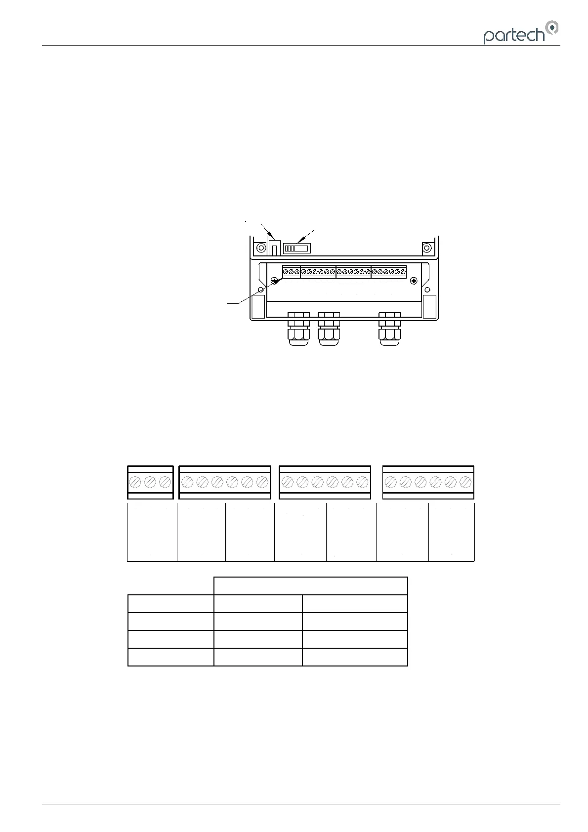
When the instrument is installed, it is essential to check that the supply voltage selector switch position is correct for
the intended supply voltage. If this is not checked the instrument could be damaged. The voltage selector is shown
below
COM
LIVE
NEUTRAL
N/C
N/O
COM
N/C
N/O
COM
N/C
EARTH
ALARM 2
ALARM 1
INPUT
12V
INPUT
0V
12V
12V
N/O
GND
N/O
0V
2
Fuse
Voltage Selector
Connection Terminals
FAULT
CLEAN O/P SENSOR 1 SENSOR 2
The electrical supply to the unit should be installed such that there is a means of isolating the supply to the unit and
the supply is protected with a fuse or trip. The instrument has a supply fuse fitted internally.
The 8100 monitor is supplied with three PG11 cable glands fitted and has provision for a further PG11 gland, whereas
the 8200 comes with four fitted cable glands. If any fitted cable glands are not being used then the glands must be
sealed to prevent the ingress of moisture into the unit.
Shown below are the terminal connections for the 8100/8200 Monitor.
COM
LIVE
NEUTRAL
N/C
N/O
COM
N/C
N/O
COM
N/C
EARTH
ALARM 2ALARM 1
SENSOR I/P
12V
SENSOR I/P
0V
12V
12V
N/O
GND
N/O
0V
POWER
FAULT
SENSOR 1
CLEAN O/P
SENSOR 2
Sensor Type
Terminals IR Series Sensor ST Series Sensor
Sensor I/P White White
Sensor 12V Red Red
Sensor 0V Black/ Blue Black/ Blue
3.1 Supply Voltage
The supply voltage for the 8100/8200 Monitor is available in 115/230VAC (switchable), 12VDC or 24VDC versions.
The voltage can be selected between either 115VAC or 230VAC by switching the selector switch, located behind the
front cover. To gain access to the voltage selector remove the four black screws from the blue front panel. The voltage
selector switch is then visible in the bottom left corner, located alongside the fuse.
168270IM-02 Issue Date 05/01/2010 Page 7 of 14