8
Note the pressure arm should be adjusted in order to give
the minimum amount of pressure on the wire to allow reliable
feeding,
5.7 Welding wire installation
1. Open the Wire Drive Compartment Door by lifting the 2 nger
catches on the side panel.
2. Unscrew the plastic retaining wheel from the end of the spool
holder shaft.
3. Position the wire spool so that it will rotate in a direction when
feeding so as to be de-reeled from the bottom of the coil.
4. Slide the wire spool all the way onto the shaft and ret the
plastic retaining nut.
Note:- there is a friction brake on the reel hub assembly to
prevent the wire spool over running when welding stops ensure
the this is slackened to the minimum setting. I can be adjusted
by means of the nut visible when the plastic nut is removed.
Fig 1 Fig 2
5. Turn the Spool until the free end of the electrode is accessible.
While securely holding the electrode, cut off the bent end and
straighten the rst six inches. (If the electrode is not properly
straightened, it may not feed properly through the wire drive
system Manually feed the wire from the wire reel and through
the wire guide and then over the top of the wire feed roller
(ensure the pressure arm is in its raised position.)
6. Continue to feed the wire through the outlet guide until 20mm of
wire is protruding from the front of the machine torch connector.
7. Reposition the adjustable pressure arm to its original position to
apply pressure. Adjust pressure as necessary.
Note the pressure arm should be adjusted in order to give
the minimum amount of pressure on the wire to allow reliable
feeding,
5.7 torch installation
Your Parweld MIG/MAG Welding Torch has been supplied ready to
weld. It has been supplied with the standard consumables denoted
in the product brochure.
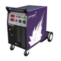
To connect the torch to the power source:-
1. Remove the tip adaptor and contact tip
2. Inch the wire from the exit of the wire guide on the feed unit
as Figure 1. Ensure that it does not short out on any machine
panels.
3. Carefully slide the electrode wire into the torch liner and
slowly locate the torch gun plug body into the feed unit central
connector and tighten the gun plug nut as Figure 2
Note; To aid the initial location of a new torch and to prevent
damage to the gas nipple O-ring a very light application of
grease to the O Ring is benecial.
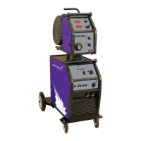
4. Keeping the torch as straight as possible, use the power source
inch facility or torch trigger to feed the electrode wire 50mm
from the end of the liner conduit.
5. Once the electrode wire has stopped, ret the tip adaptor,
diffuser, contact tip and gas nozzle.
6. Trim the electrode wire to within 5mm of the face of the nozzle,
this will facilitate jolt free arc initiation.
7. Press the gas purge button and check the gas ow is adequate
for your application.
8. An inexpensive ow meter is available from Parweld reference
806001.
9. If you are setting a water-cooled torch ensure you have the
recommended water ow rate.
Note;- It is essential to ensure adequate ow of clean, cool
water to prevent irreparable torch failure, a minimum of 1.2 l/
min is recommended.
Parweld recommend the use of its XTS water recirculation system
designed specically for use with all water cooled MIG, TIG and
Plasma welding torches.
The Parweld XTS recirculation equipment can be tted with a fail-
safe ow protection device to prevent overheating or meltdown.
Note. Water ows into the torch through the blue hose. The blue
hose delivers cold water directly to the prime source of heat, the
swan neck and consumable. The re circulated water is then passed
through the torch power cable to cool the power cable as it is
returned to the cooler through the red water return lead.
Ensure all air is removed from the water cooling circuit before
welding.
5.8 Work return lead connection
Insert the work return lead connector into the receptacle on the front
panel of the machine and twist it clockwise until tightly secured.
Connect the earth clamp to the work piece as close as possible to
the point to be welded and ensure that a good electrical connection
is created to bare metal.
5.9 Shielding gas connection