DATASHEET
AX6000 SERIES
3
1. INTRODUZIONE
Gli amplificatori AX6120 e AX6240 sono dotati di una CPU interna in grado
di gestire selezioni, funzioni Chime/VOX e postazioni microfoniche.
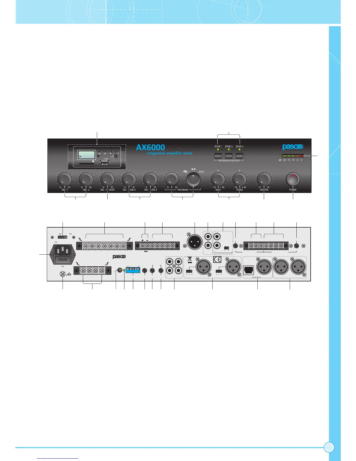
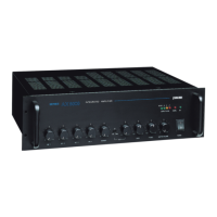
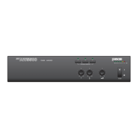
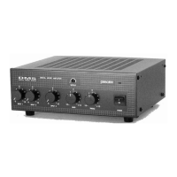
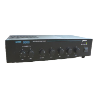
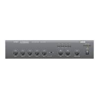
1.1 Pannello frontale
1. Controlli di livello ingressi microfonici.
2. Controllo di livello ingresso microfonico/unità.
3. Controlli di livello ingressi microfonici/linea.
4. Controllo di livello e selezione ingressi ausiliari.
5. Controlli di tono.
6. Controllo di volume generale.
7. Interruttore di rete.
8. Visualizzatore del livello d’uscita.
9. Tasti inserzione musica.
10. Lettore SD CARD/USB (opzionale).
1. INTRODUCTION
Amplifiers AX6120 and AX6240 have an internal CPU capable of managing
the selections, the Chime/VOX functions and microphone stations.
1.1 Front panel
1. Level control for microphone inputs.
2. Microphone input/unit level control.
3. Microphone input/line level control.
4. Level control and selection of auxiliary inputs.
5. Tone controls.
6. General volume control.
7. Mains switch.
8. Output level indicator.
9. Music activation keys.
10. SD CARD/USB reader (optional).
132 6 7
8
910
SD CARD & USB PLAYER
PREV NEXT STOP PLAY
IR
SD/MMC CARD
USB
REPEAT
PAUSE
0000
4 5
115V 230V
V 50/60Hz - 360VA
FUSE T2,5A
L
100V70V50V8W0V0V0V
V IN
Z3
Z2Z1
SET
CHIME
SETTINGS
MIC.1 TEL./EM.
TAPE
CD MIC./LINE 5 MIC./LINE 4
MIC.3UNITS
MIC.2 MIC.1
L
R
24V
12A
BAL. LINE OUT TAPE OUT
PWR IN
PRE OUT
PH.
MIC. LINE
PH.
MIC. LINE
ON OFF
HOT COM GND GND MON HOT COMLEV.
1W - 8W 1V - 600W
LINK
LEV.
TEL. / EMERG. MUSIC ON HOLD
L
R
AMPLIFIER AX6120
POWER RATING 120 W
CAUTION: DO NOT OBSTRUCT
THE OPENING. REPLACE FUSE
WITH SAME TYPE AND VALUE
D LEV. A.P.T.ADDRESS
IN
ON
1234 567 8
+24V OVR GND PR +12V
34
33
32
31
26
27
25
24
22
21
28
29
30
13 1615
14
17 18
19
2012
11
23
1.2 Pannello posteriore
11. Spina di rete con fusibile incorporato.
12. Connessione telaio.
13. Morsettiera selezione zone.
14. Pulsante impostazioni.
15. Led conferma acquisizione impostazioni.
16. Dip-switches impostazioni.
17. Regolazione di livello del segnale di preavviso.
18. Regolazione soglia d’attivazione precedenza ingresso MIC.1.
19. Regolazione soglia d’attivazione precedenza ingresso TEL./EMERG.
20. Ingressi ausiliari.
21. Ingressi MIC/LINE 4-5 e relativi selettori di modalità funzionamento.
22. Ingresso MIC3/Unità Serie PMB.
23. Ingressi microfonici.
24. Regolazione di livelllo uscita MUSIC ON HOLD.
25. Uscite di linea e di potenza MUSIC ON HOLD.
26. Ingresso emergenza da centralino telefonico.
27. Regolazione di livello ingresso telefonico.
28. Presa per equalizzatore esterno.
29. Uscita per registratore.
30. Uscita di linea bilanciata.
31. Connessioni precedenza e override.
32. Morsettiera per alimentazione esterna in corrente continua.
33. Morsettiera uscita altoparlanti.
34. Selettore della tensione di rete.
1.2 Rear panel
11. Mains plug with built-in fuse.
12. Frame connection.
13. Zone selection terminal strip.
14. Push-button for settings.
15. LED for confirming acquisition of settings.
16. DIP switches for making settings.
17. Level control of the warning signal.
18. MIC.1 input precedence activation threshold adjustment.
19. TEL./EMERG. input precedence activation threshold adjustment.
20. Auxiliary inputs.
21. MIC/LINE inputs 4-5 and relevant operating mode selector switches.
22. MIC3/PMB range Unit input.
23. Microphone inputs.
24. MUSIC ON HOLD output level adjustment.
25. MUSIC ON HOLD line and power outputs.
26. Emergency input from PABX.
27. Telephone input level adjustment.
28. Socket for an external equaliser.
29. Output for recorder.
30. Balanced line output.
31. Precedence and override connections.
32. Terminal strip for external DC power supply.
33. Loudspeakers output terminal strip.
34. Mains voltage selector switch.