PROFESSIONAL AUDIO & SOUND
®
TM
DIGITAL MUSIC SERIES
DIGITAL MUSIC AMPLIFIERS
INSTALLATION AND WIRING
PAGE 17
SPECIFICATIONS ARE SUBJECT TO CHANGE WITHOUT NOTICET3015/3030DMA
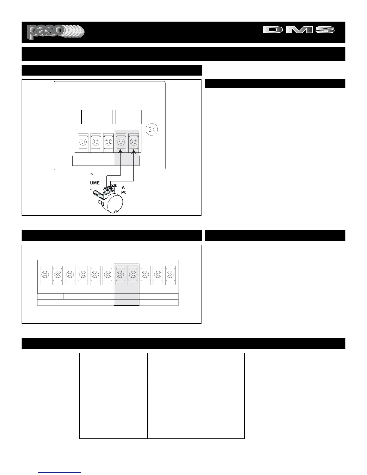
REMOTE MASTER VOLUME
The Amplifier features a Remote Volume Control Input. A
50 KB Potentiometer and Knob are supplied with the
Amplifier. Mount the Control on a suitable Wall Plate or any
other convenient surface and connect to the Amplifier
REMOTE VOLUME Terminals as shown in the Diagram.
OPERATION
The Control is a Master Volume and controls all the 3
Inputs of the Amplifier with the exception of the MOH and
ZONE 1 and ZONE 2 Outputs.
CABLE
To connect the Remote Control to the Amplifier use a two
conductor wire not less than AWG 24. While the Remote
Volume System uses DC rather than audio caution should
be exercised in the layout of the wire. Always avoid routing
next to power lines. If the total wire resistance exceeds 3 K
ohm the Volume may not go down to zero.
REMOTE MASTER VOLUME
REMOTE MASTER VOLUME CONTROL
INPUT 1
RVC
MIC/TEL
REM
VOLUMEBALANCED
REMOTE
V
HOTG COM
REM
TE V
NTR
50 K
REM
TE V
L
ME
NTR
TENTI
METER I
PPLIE
1
B Remote Volu
Fig. 17 - Remote Volume Control Connection Diagram
POWER SUPPLY
The Amplifier provides a 24 Volt DC Regulated Auxiliary
Power Supply Output at 100 mA current.
CABLE
To connect the Power Supply Output to accessories use a
two conductor wire not less than AWG 18. This minimum
wire gauge is necessary to minimize potential Voltage
Drops in long wire connection applications. For wire resist-
ance refer to Table below.
CAUTION: Be sure that the 24 V DC Output Terminals are
not shorted during installation.
24 VOLT POWER SUPPLYREGULATED AUXILIARY POWER SUPPLY
NC NOC+-
000
RELAY
VOX
24V DC
100 mA
1 WATT
ZONE 2
ZONE 1
1 VOLT
8
OHM
8
OHM
600
OHM
Fig. 17B - 24 Volt Power Supply Output Diagram
WIRE GAUGE - RESISTANCE TABLE
WIRE RESISTANCE IN
AWG OHMS per 1000 Ft.
16 4.016
18 6.385
20 10.15
22 16.14
24 25.67
26 40.81
NOTE:
When calculating the Wire
Resistance for each run using a
two conductor Wire the wire
Resistance should be doubled.
EXAMPLE: The Total Resistance
of a 1000 Ft. run of a AWG 24 two
conductor Wire is:
25.67 X 2= 51.34 Ohm