UNSWITCHED 117V 500W MAX.
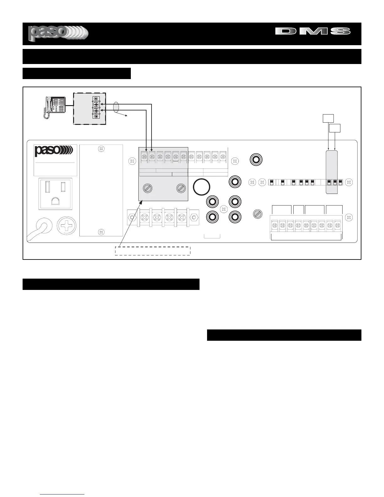
Fig. 19 - Rear Panel MOH Connection Diagram
MOH/ZONE 1 AMPLIFIER SOURCE SELECTOR
MOH AMPLIFIER
The Integrated Amplifier provides an independent 600 ohm, 1 Volt
Output, Transformer Balanced MUSIC-ON-HOLD Amplifier . The Input
Source of the MOH Amplifier can be selected from either the INPUT 2
or the INPUT 3.
MOH - 600 OHM SYSTEM
Most Phone systems operate on a 600 ohm Input Impedance, if the
Impedance required is 600 ohm connect the Amplifier to the Phone
System MOH by using the diagram above.
MOH - 8 OHM, 1 WATT SYSTEM
Some older Key Phone systems require a 1 watt Power Output having
an Output Impedance of 8 ohm to drive the Music on Hold feature. If
the Impedance required is 8 ohm connect the Phone system MOH to
the 8 ohm, 1 Watt MOH Output of the Amplifier. See Diagram above.
CABLE
Use a cable consisting of a twisted pair of at least AWG 18. Use care
in extending the cable and avoid routing near power lines, fluorescent
lights and other systems that may generate a disturbing electric field.
SOURCE SELECTOR
Select the Input Source desired by following the instructions at right.
MUSIC ON HOLD AMPLIFIER
MOH/ZONE 1 SOURCE SELECTOR
The Source for the MOH/ZONE 1 Amplifier can be selected
between the INPUT 2 and the INPUT 3 by setting the Selector
Switch provided for this purpose. The Amplifier is shipped
from the Factory with the Selector Switch set for INPUT 2. To
change the setting do the following:
ACCESS TO THE MOH/ZONE 1 INPUT SOURCE SELEC-
TOR
1) Remove Power Cord from AC Outlet.
2) Remove the two screws on each side of the Transparent
Plastic Cover Protecting the Selector Switches on the rear
panel.
3) Lift Cover and set appropriate Switch(es) to required set-
ting(s).
4) Replace protective cover.
LEVEL CONTROL
After the wiring is completed adjust the MOH/ZONE 1
Amplifier Level Control on the rear panel to the desired output
level.