PROFESSIONAL AUDIO & SOUND
®
TM
DIGITAL MUSIC SERIES
DIGITAL MUSIC AMPLIFIERS
PAGE 6
SPECIFICATIONS ARE SUBJECT TO CHANGE WITHOUT NOTICE T3015/3030DMA
INPUT 1 SETTING AS A MICROPHONE INPUT
MICROPHONE TYPE
The Microphone Input accepts Low Impedance (250-600 ohm)
Dynamic Microphones.The Microphone may be a balanced output
type (three wire) or an unbalanced output type (two wire).
PASO MICROPHONES
All PASO low impedance Microphones have a balanced output for
best performance. Connect the RED lead to terminal HOT, the
WHITE lead to terminal COM and the SHIELD to terminal G (see
Fig. 6).
WIRING
CABLE
INSTALLATION AND WIRING
3015Bmicbal
The microphone leads color refers to Paso
Microphones only. When using other brand
refer to instructions packed with that unit.
SHIELD
MIC
Lo Z
RED
THREE LEADS BALANCED MICROPHONE WIRING
WHITE
INPUT 1 - Switch Setting
INPUT 2
INPUT 1
RVC
MIC/PROG MIC/TEL
REM
BALANCED VOLUMEBALANCEDMUTE
MUTE REMOTE
VOL
HOTGCOM COMG
HOT
I
N
P
U
T
1
TEL Prog
CD Off
Off Off
MIC MIC
I
N
P
U
T
2
I
N
P
U
T
3
I
N
P
U
T
1
I
N
P
U
T
2
I
N
P
U
T
2
Z
O
N
E
1
Z
O
N
E
2
E
Q
L
I
N
K
Off
Vox
On
Mute
On
Vox
On
Aux
INPUT
3
INPUT
2
On
3015Bmicunbal
The microphone leads color refers to Paso
Microphones only. When using other brand
refer to instructions packed with that unit.
MIC
Lo Z
RED
INPUT 1 - Switch Setting
INPUT 2
INPUT 1
RVC
MIC/PROG MIC/TEL
REM
BALANCED VOLUMEBALANCEDMUTE
MUTE REMOTE
VOL
HOTGCOM COMG
HOT
I
N
P
U
T
1
TEL Prog
CD Off
Off Off
MIC MIC
I
N
P
U
T
2
I
N
P
U
T
3
I
N
P
U
T
1
I
N
P
U
T
2
I
N
P
U
T
2
Z
O
N
E
1
Z
O
N
E
2
E
Q
L
I
N
K
Off
Vox
On
Mute
On
Vox
On
Aux
INPUT
3
INPUT
2
On
TWO LEADS UNBALANCED MICROPHONE WIRING
SHIELD
MICROPHONE INPUT
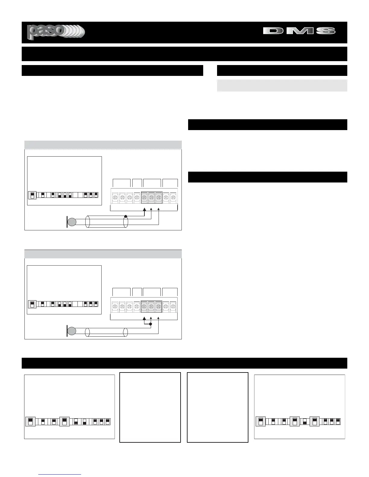
Attach the microphone leads to the terminal strip as per diagram
in Fig 6 or Fig. 6A.
DO NOT GROUND THE MICROPHONE CABLE SHIELD TO THE
CHASSIS OF THE AMPLIFIER
Fig. 6A - Unbalanced Microphone Input 1 Wiring
BALANCED MICROPHONE
IMPORTANT NOTE: The use of an unbalanced Microphone (two
leads) is not recommended. For best results in a PA Application
always use a Unidirectional Dynamic, Low Impedance, Balanced
Microphone (three leads).
CABLE LENGTH - If the distance between the Microphone and
the Amplifier Input is greater than 15 ft (4.5 m) a Balanced
Microphone must be used. Use a two conductor shielded wire and
connect Microphone to Amplifier as per Diagram in Fig. 6.
MICROPHONE CABLE ROUTING - The Microphone Cable
should be carefully routed. Improper Cable routing will cause spu-
rious oscillations, regenerative noises, hum, etc. that may perma-
nently damage the Amplifier.
z Do not route cable next to power lines.
z
Do not route cable near or over Fluorescent
Fixtures.
z
Do not route cable next to Speaker Wires.
z
Do not install cable inside Power Line Conduits.
z
Avoid the use of staples that may penetrate the
cable.
UNBALANCED MICROPHONE
Attach the Microphone leads to the terminal strip as per diagram
in Fig 6A. The cable length should not exceed: 15 Ft. (4.5 m).
Fig. 6 - Balanced Microphone Input 1 Wiring
SET INPUT 1 SWITCH TO MIC
INPUT SWITCH SETTING
CAUTION:
TO PREVENT POSSIBLE DAMAGE TO SPEAKERS
OR THE AMPLIFIER ALL INPUT CONNECTIONS MUST BE
MADE WITH THE AMPLIFIER OFF (POWER OFF).
MUTING - PRIORITY SETTINGS
Switch Settings
I
N
P
U
T
1
TEL Prog
CD Off
Off Off
MIC MIC
I
N
P
U
T
2
I
N
P
U
T
3
I
N
P
U
T
1
I
N
P
U
T
2
I
N
P
U
T
2
Z
O
N
E
1
Z
O
N
E
2
E
Q
L
I
N
K
Off
Vox
On
Mute
On
Vox
On
Aux
INPUT
3
INPUT
2
On
Switchset01
Switch Settings
I
N
P
U
T
1
TEL Prog
CD Off
Off Off
MIC MIC
I
N
P
U
T
2
I
N
P
U
T
3
I
N
P
U
T
1
I
N
P
U
T
2
I
N
P
U
T
2
Z
O
N
E
1
Z
O
N
E
2
E
Q
L
I
N
K
Off
Vox
On
Mute
On
Vox
On
Aux
INPUT
3
INPUT
2
On
Switchset02
MUTING INPUT 3
To mute Input 3 (Music)
when Paging from MIC 1,
set INPUT 1 VOX Switch
to the ON Position. See
Diagram at left. Each time
MIC 1 is activated the
Program on Input 3 is
automatically muted by the
VOX.
MUTING INPUTS 2 & 3
To mute Inputs 2 & 3
when Paging from MIC 1,
set INPUT 1 VOX Switch
and INPUT 2 MUTE
Switch to the ON Position.
See Diagram at right.
Each time MIC 1 is activat-
ed the Programs on Input
2 & 3 are automatically
muted by the VOX.