PROFESSIONAL AUDIO & SOUND
®
TM
DIGITAL MUSIC SERIES
DIGITAL MUSIC AMPLIFIERS
PAGE 7
SPECIFICATIONS ARE SUBJECT TO CHANGE WITHOUT NOTICET3015/3030DMA
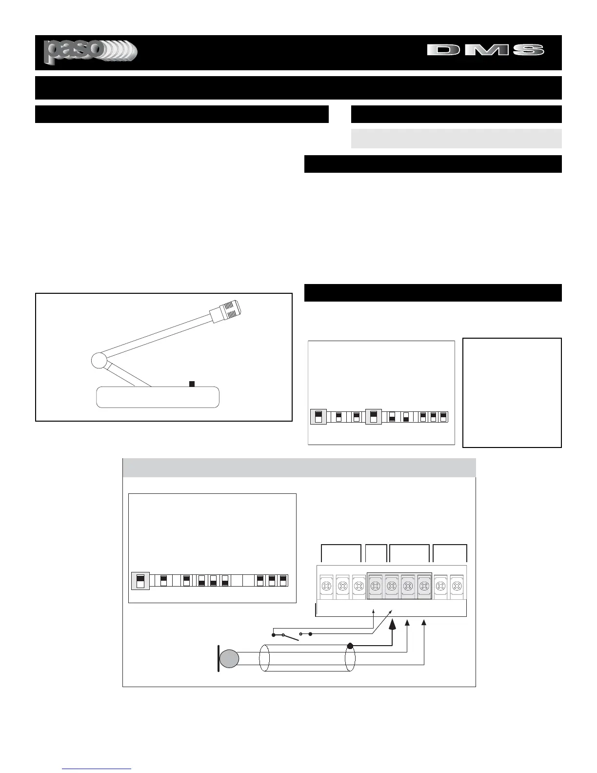
USING A PUSH-TO-TALK DESK BASE MICROPHONE
Microphone paging and precedence over the AUX or PROGRAM
channels may be accomplished by using a Desk Base or a
Gooseneck Microphone. Wire the Microphone output leads to the
MIC input terminals as per Fig. 7B.
MUTING: The Amplifier is equipped with two independent Muting
Circuits:
z Direct Muting by shorting the MUTE Terminals
z
Automatic Muting with VOX - Voice Activated Muting
For additional information on the Muting operation
refer to the Muting Functions section of this Manual.
WIRING
INSTALLATION AND WIRING
3015Bmicbase
Connect Desk Base or Gooseneck Microphone
as per diagram below. Connect Muting Switch
to MUTE and G Terminals. If using VOX system
the muting switch is unnecessary.
SHIELD
MIC
Lo Z
B
DESK BASE/GOOSENECK MICROPHONE WITH MUTING SWITCH
A
INPUT 1 - Switch Setting
INPUT 2
INPUT 1
RVC
MIC/PROG MIC/TEL
REM
BALANCED VOLUMEBALANCEDMUTE
MUTE REMOTE
VOL
HOTGCOM COMG
HOT
I
N
P
U
T
1
TEL Prog
CD Off
Off Off
MIC MIC
I
N
P
U
T
2
I
N
P
U
T
3
I
N
P
U
T
1
I
N
P
U
T
2
I
N
P
U
T
2
Z
O
N
E
1
Z
O
N
E
2
E
Q
L
I
N
K
Off
Vox
On
Mute
On
Vox
On
Aux
INPUT
3
INPUT
2
On
MUTING SWITCH
Fig. 7B - Input 1 and Muting Terminals
Wire the Desk Base Microphone leads to the Microphone
Input terminal strip as per diagram in Fig 7B. Check
Microphone instructions and connect HOT LEAD (B) to
Terminal HOT, COMMON LEAD (A) to Terminal COM and
SHIELD LEAD to Terminal G. Connect Muting Switch to
Terminals MUTE and G as shown.
DO NOT GROUND THE MICROPHONE CABLE SHIELD
TO THE CHASSIS OF THE AMPLIFIER
b50side
Push to Talk Key
Fig. 7A - Desk Base Microphone
INPUT 1 SETTING AS A MICROPHONE INPUT
SET INPUT 1 SWITCH TO MIC
INPUT SWITCH SETTING
MUTING - PRIORITY SETTINGS
Switch Settings
I
N
P
U
T
1
TEL Prog
CD Off
Off Off
MIC MIC
I
N
P
U
T
2
I
N
P
U
T
3
I
N
P
U
T
1
I
N
P
U
T
2
I
N
P
U
T
2
Z
O
N
E
1
Z
O
N
E
2
E
Q
L
I
N
K
Off
Vox
On
Mute
On
Vox
On
Aux
INPUT
3
INPUT
2
On
Switchset01
MUTING INPUT 3
To mute Input 3 (Music)
when Paging from MIC 1,
set INPUT 1 VOX Switch
to the ON Position. See
Diagram at left. Each time
MIC 1 is activated the
Program on Input 3 is
automatically muted by the
VOX.
Direct Muting is provided by the Desk Base Muting Switch wired as
per diagram in Fig. 7B. If Auto-Mute (VOX) is desired follow instruc-
tions below. The Desk Base Muting Switch can be omitted.