33
Buzzer Unit Underside View
DIP Switch
(
When down, it is "ON"
)
Switch is shown by ■.
Point
12
3
4
5
6
7
8
②Buzzer
M12 Connector Pin Layout
③LED Green
④LED Amber
⑤Power Supply Wire
⑧Power Supply Wire
⑥LED Red
M12 Connector Cable (Optional Part)
Refer to pg 83 for “Optional Parts”.
※Not included with this product.
M12 Connector
⑦LED Blue
①LED White
.
It is recommended
to use the M12
Connector Cable
(Optional Part) for
wiring.
Attach the M12 connector cable to the body unit
WC
WC
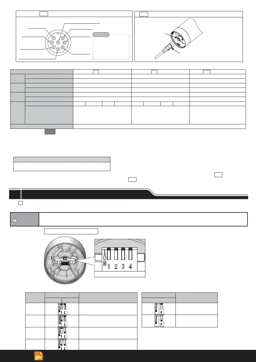
The
Flashing/Buzzer type includes a set up for four different patterns and sound reduction.
Set up the preferred pattern, using the DIP Switch after removing the buzzer unit.
DIP Switch
OFF
Normal
Sound Reduction
Volume
12
OFF OFF
ON
OFF
OFF ON
ON ON
Rapid Hi-Lo
Sweep Sound
DIP Switch
Sound Pattern
Continuous Beep Sound
■ Pattern Setup Table
Buzzer
Sound
No.1
No.2
No.3
No.4
〈
Note
〉
Do not use DIP Switch 4.
It is set to "OFF" at all times after
factory shipments.
3
Rapid Intermittent Beep
ON
●
Do not use excessive force
to set up the switches. Possible damage or malfunction may occur.
●
Do not adjust switches with a sharp object.
Possible damage to switches may cause it to be impossible to operate or
cause partial movement of the contacts.
Caution
〈Note〉
●
When a regulated power supply is not being used, select a fuse that meets class CC or more ( ).
●
Use a fuse holder with UL standard certification ( ).
● Be sure the power is disconnected before changing fuses.
■Recommended Fuse
■External Contact Capacity
Fuse Rated Current
250V / 1A
5x20mm Fast-Acting Glass Body Cartridge Fuse
Inrush
Current
LED Unit
(1 Tier)
Buzzer
Rated Load Voltage
Power
Supply
Leakage Current
Signal Wire Current (Max.) / Voltage
Recommended Contact Capacity
Signal Wire Current (Max.) / Voltage
Recommended Contact Capacity
Current Consumption (Max.)
Recommended Contact Capacity
Signal Wire
Power Supply Wire
100 mA / Power Supply Voltage
250 mA / Power Supply Voltage
Is ≧ 100 mA Vs ≧ 20 V DC(※1)
Is ≧ 300 mA Vs ≧ 20 V DC(※1)
500 mA(※2)
Is ≧ 700 mA Vs ≧ 20 V DC
I
L ≦0.1 mA
None(※1)LED Buzzer None(※1)
0.7A / Less than 15ms
45 mA / 24V DC
250 mA / 24 V DC
Is ≧ 100 mA Vs ≧ 35 V DC
Is ≧ 300 mA Vs ≧ 35 V DC
150mA(※2)
Inrush current or more contacts
Is:Current Capacity Vs:Withstand Voltage IL:Leakage Current Ta:Ambient Tenperature
None
Ta=25℃:25A /
Less than 2ms (Cold-start)
Ta=50℃ :50A /
Less than 2ms (Cold-start)
12 V DC
01
100 - 240 V AC
M2
02
24 V DC
45 mA / Power Supply Voltage
250 mA / Power Supply Voltage
Is ≧ 100 mA Vs ≧ 35 V DC
Is ≧ 300 mA Vs ≧ 35 V DC
250 mA(※2)
Is ≧ 500 mA Vs ≧ 35 V DC
None
(※4)
※
1 … When the ( ) power supply wire is not connected,inrush current of 0.7A will flow through the signal wire.
Recomended Contact Capacity : Is
≧
700 mA
Vs
≧
20 V DC
※
2 … Measured with five LED tiers and buzzer operating.
※
3 … Not exceeding Maximum Signal Wire Current Rating.
※
4 … Signal Wire Current (Max.) not exceeding the sum of total.
NoneLED Buzzer None(※3)
Gray
M2
M2
B
Buzzer Pattern Set-up
6
ghv Vertriebs-GmbH | Am Schammacher Feld 47 | 85567 Grafing | Telefon + 49 80 92 81 89 0 | info@ghv.de | www.ghv.de
 Loading...