19
3
1
20
3
1
35
Opposite Side
27
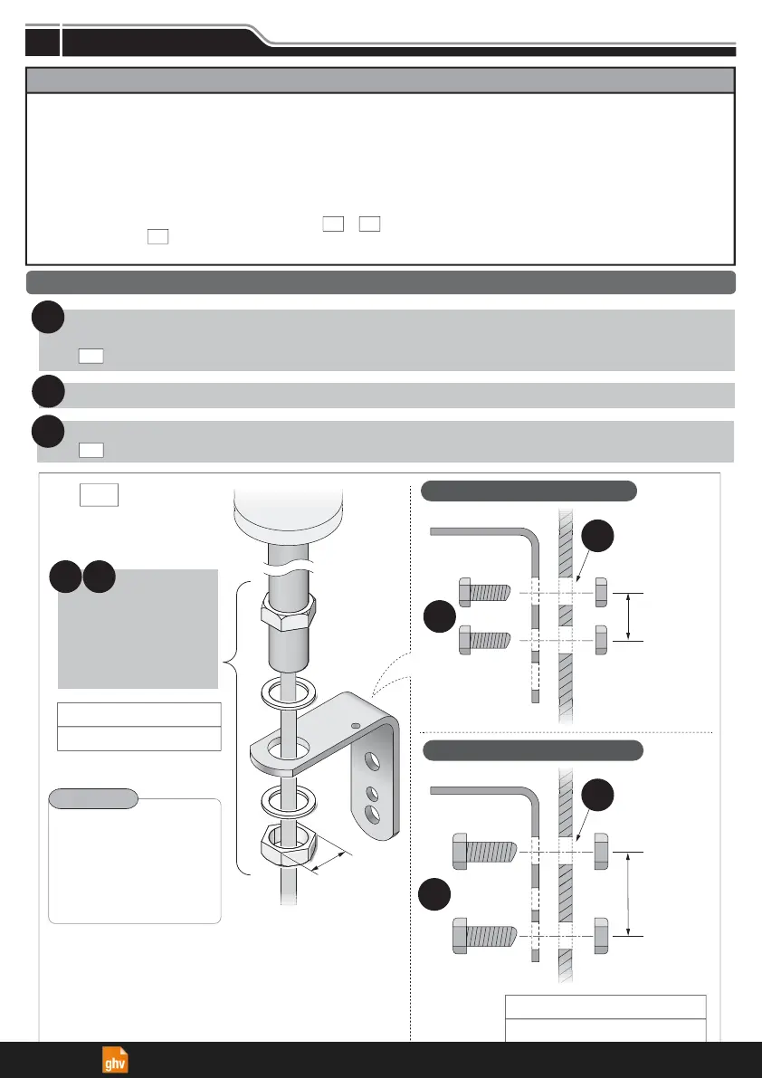
Make holes for the mounting and wire-distribution for the product.
(Check the Model and refer to the suitable attachment or mounting dimension figure.)
( Select among the two mounting options.)
1
Run the wiring through the distribution hole.
2
Secure the product with the bolts, nuts and screws.
( required nuts and screws are not included.)
3
Notice
LJ
Basic Mounting Instructions
Installation
Figure
■
LJ
When not using a
L-bracket attachment,
make a fitting hole
of
φ
22-23mm.
12.2 N
m
Recommended screw Torque
30 N
m
Recommended Nut Torque
Point
Feed the wiring
through the hole
and set the pole
in place to install.
32
Mounting
Surface
(Unit: mm)
L-bracket
Mounting
Hole
(
φ
9)
Mounting
Surface
L-bracket
Mounting
Hole
(
φ
11)
For M8 screw and nut size
For M10 screw and nut size
● The following requirements are necessary for proper installation:
- Install the signal tower where excessive vibration is not present.
- Install the signal tower on a sturdy surface.
- Install the signal tower on a level surface.
● Install the signal tower in an upright position only.
● When the installation location is unavoidably irregular and waterproof performance is required, use a sealant between
the product and the installation surface.
● If the pole type requires an IP65 rating, apply sealant to the screws, nuts and wire distribution hole when installing the
compatible bracket onto the installation surface. ( )
● Although the LR4- mounting bolt moves prior to assembly, it is not a quality issue. Be sure to mount the product in
the manner indicated below.
KT
PJ
・
QJ
WJ
Installation
4
ghv Vertriebs-GmbH | Am Schammacher Feld 47 | 85567 Grafing | Telefon + 49 80 92 81 89 0 | info@ghv.de | www.ghv.de