EasyManua.ls Logo

PAVONE DAT 500 User Manual

PAVONE DAT 500
56 pages
To Next Page IconTo Next Page
Page #1 background imageLoading...
Page #1 background image
DAT 500
TECHNICAL MANUAL
For Analog/Probus/Devicenet versions
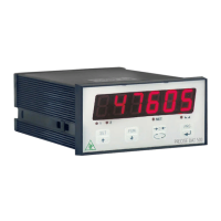
Digital Transmitter
Software version PW13081

Questions and Answers:

PAVONE DAT 500 Specifications

General IconGeneral
BrandPAVONE
ModelDAT 500
CategoryTransmitter
LanguageEnglish

Summary

Precautions and Safety Warnings

Read and Follow Instructions

Read the manual before operating or servicing the instrument and save for future use.

Qualified Personnel Only

Installation and maintenance must be performed by qualified personnel; exercise caution with live instrument.

Introduction to the DAT 500 Transmitter

General Warnings

Important warnings stating procedures require qualified personnel and connections must be made with the instrument off.

Installation Guide

Electrical Installation Details

Guidance on screw terminal boards, load cell cable shielding, and power supply connections.

Instrument Power Supply

Connecting and supplying power to the instrument, including voltage isolation and consumption.

Load Cell Connections

Load Cell Cable Routing

Guidelines for routing load cell cables separately from other cables to prevent interference.

Load Cell Capacity and Sensitivity

Connecting up to 8 load cells, supply voltage, and sensitivity range for the instrument.

4-Wire Load Cell Jumper

Instructions for configuring terminals 19-24 for 4-wire load cell connections.

Fieldbus Protocols: Profibus DP

Profibus DP Pinout

Pin assignments for connecting to a Profibus Master.

Profibus Cable Specifications

Cable impedance, capacity, resistance, and conductor cross-section requirements.

Fieldbus Protocols: DeviceNet

DeviceNet Pinout

Pin assignments for DeviceNet connections.

DeviceNet Cable and Termination

Requirements for DeviceNet or shielded twisted-pair cables and line termination.

Keyboard Operation and Functions

Keyboard Functions: Weight Display

Key functions during weight display: setpoints, view toggle, zeroing, serial transmission.

Keyboard Functions: Main Menu

Key functions for navigating main menus: selecting next/previous, exiting, accessing sub-menus.

Keyboard Functions: Numerical Values

Key functions for setting numerical values: increasing/decreasing digits, moving, confirming.

Information Display and Error Codes

Error Notifications

List and description of common error codes displayed by the instrument.

Weight Viewing, Zeroing, and Self-Calibration

Zeroing and Self-Calibration

Performing zeroing and self-calibration using the →0- key.

Self-Calibration Conditions

Criteria required for self-calibration: Net mode, positive weight, stable weight.

Zeroing Procedure Details

Correcting zero shifts due to thermal drift or material accumulation.

Programming Weight Setpoints

Setpoint Functionality

Comparing setpoint values with weight to control logic outputs.

Accessing Setpoint Setting

Procedure to enter the setpoint configuration mode using the SET key.

Setpoint Adjustment

Using keys to increment, change, and confirm setpoint digits.

Parameter Setting and Configuration

General Setting Data

All settings are stored and accessible via a setup menu.

Accessing the Setup Menu

Procedure to enter the main setup menu by pressing PRG and SET keys.

Configuration Parameters: Full Scale Calibration

Full Scale Calibration Process

Performing full scale calibration using sample masses for system accuracy.

CAPAC: Capacity of Weighing System

Setting the total rated capacity of load cells for the weighing system.

SENSIT: Load Cells Sensitivity

Setting the average sensitivity of load cells in mV/V.

Automatic Parameter Adjustment

How CAPAC, SENSIT, NET, DEAD L affect auto-adjustment of other parameters.

Capacity and Sensitivity Configuration

Net Capacity Setting

Programming the net capacity, with minimum value constraint relative to CAPAC.

DEAD L: Fixed Calibration

Programming the fixed calibration value for the weighing system.

dSPd IU: Division Value

Setting the division value to define system resolution and affect calibration.

Data Transfer and Calibration Example

Setting/Calibration Example

Step-by-step guide for configuring parameters for a specific weighing task.

Example Parameter Values

Specific values provided for CAPAC, SENSIT, NET, DEAD L, and dSPd IU.

Calibration Procedures

Calibration Requirements

Using sample masses or pre-weighed product for accurate calibration.

Zero Calibration Procedure

Performing zero calibration when the scale is empty and the weight is stable.

Full Scale Calibration Procedure

Loading sample weight, stabilizing, and entering the theoretical weight value.

Calibration Error Notes

Verifying mechanical constraints if linearity errors appear post-calibration.

Linearization Process

Linearization Point Acceptance

Rules for accepting sample weights for linearization points.

Load Weight Entry for Linearization

Entering load weight values for specific linearization points (P1 to P9).

Input/Output Parameters: Setpoints

Node: Setpoint Operation Mode

Selecting operation criteria for setpoint 1: Net, Gross, or Peak.

Setpoint 2 Configuration

Setpoint 2 Operation Mode

Selecting operation criteria for setpoint 2: Net, Gross, or Peak.

Serial Output Parameters

Baud Rate COM1 Configuration

Setting the baud rate for the RS232 serial port (COM1).

Serial Communication Addressing

Serial Communication Protocols

Modbus RTU Protocol

Communication Error Handling

Modbus Holding Registers List

Register Map Overview

List of Modbus registers with address, R/W status, format, and notes.

Status and Weight Registers

Registers related to status, gross/net weight, peak value, and load cell signal.

Configuration Registers

Registers for system capacity, sensitivity, division value, filter, and stability.

Setpoint and Timer Registers

Registers for setpoint operation modes, hysteresis, timers, and delays.

Fieldbus Protocol Data Exchange

Fieldbus Input Data Area Details

Fieldbus Output Data Area

Troubleshooting Guide

Display Message Troubleshooting

Resolving issues indicated by display messages like O-L, hyphens, or underscores.

Zeroing and Tare Function Problems

Troubleshooting semiautomatic zero and tare functions related to weight limits or stability.

Grounding Connections

Intrinsic Safety Barriers

Safe Area Setup Components

Components in the safe area: Model 500 transmitter and safety barriers.

Hazardous Area Connection Diagram

Wiring diagram for summing junction boxes in hazardous areas.