0
0
PRG
PRG
tEst1n LOGIC INPUTS TEST PROCEDURE
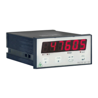
The display shows the inputs status.
0 = input disabled
1= input activated.
The input 1 corresponds to the 1a value on the left.
Enable and disable the inputs to check the corresponding state on
the display. During this procedure, the normal function of the inputs
is not active. Use this procedure only to check the hardware.
tstoUt LOGIC OUTPUTS TEST PROCEDURE.
The display shows the outputs status.
0 = output disabled, 1= output activated.
The input 1 corresponds to the 1a value on the left.
During this procedure, the LEDs reflect the state of the outputs. To set
the digits, use the keys as for the numeric settings.
During this procedure, the normal function of the outputs is not active.
Use this procedure only to check the hardware.