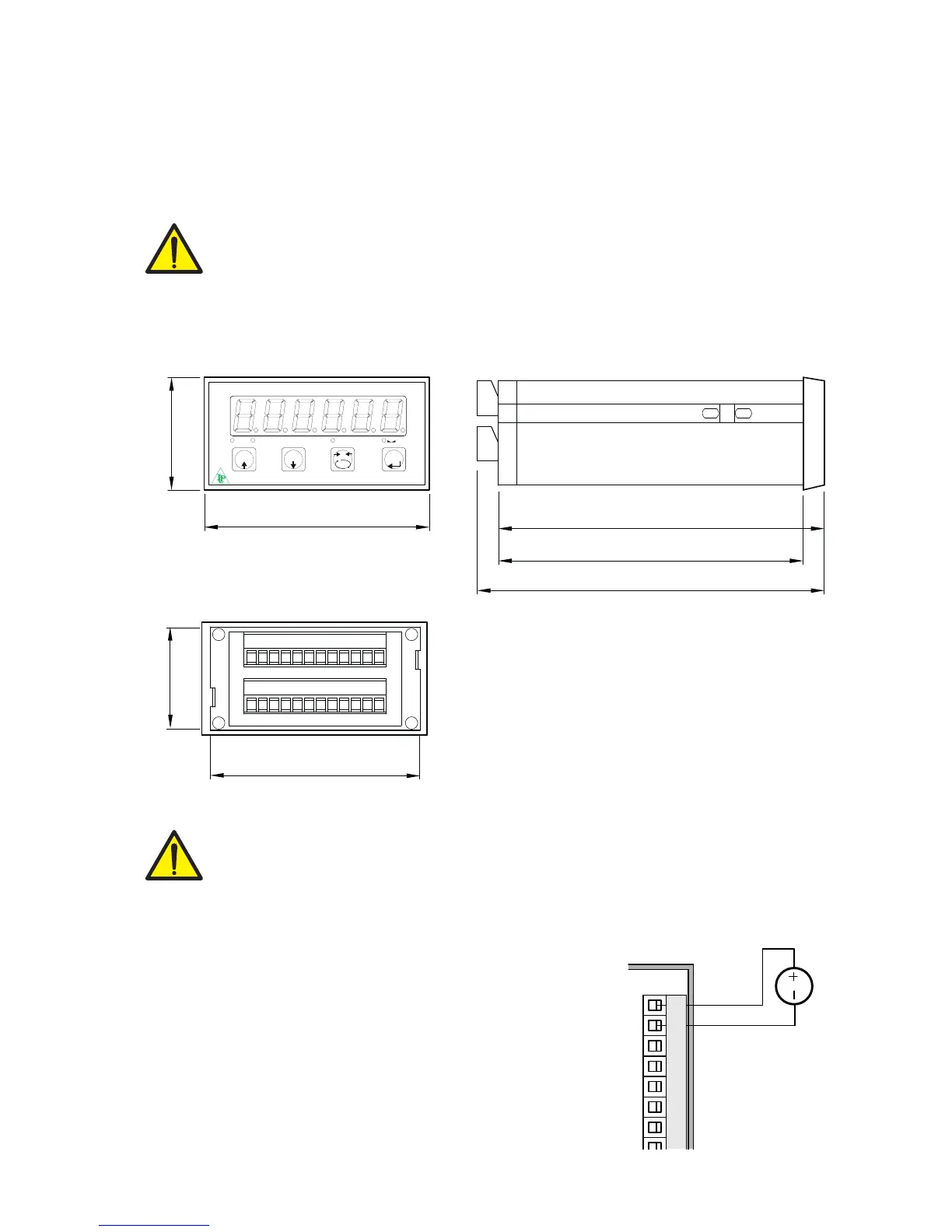
+24 Vdc
0 Vdc
INSTALLATION
GENERAL DATA
The DAT 500 is composed of a motherboard, on which you can add the options available; the mother-
board is housed in a plastic enclosure.
The DAT 500 should not be immersed in water, subjected to jets of water and cleaned or
washed with solvents.
Do not expose to heat or direct sunlight.
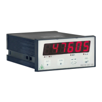
OVERALL DIMENSIONS
ELECTRIC INSTALLATION
The transmitter DAT 500 uses screw terminal boards, pitch 5.08 mm, for the electrical con-
nection. The load cell cable must be shielded and channeled away from tension cables to
prevent electromagnetic interference.
INSTRUMENT POWER SUPPLY
The instrument is powered through the terminals 1 and 2. The power
cord must be channeled separately from other cables.
The supply voltage is electrically isolated.
Power supply voltage: 24 Vdc/ ± 15% max. 5W.