For the installer – EN
13
User and installation guide
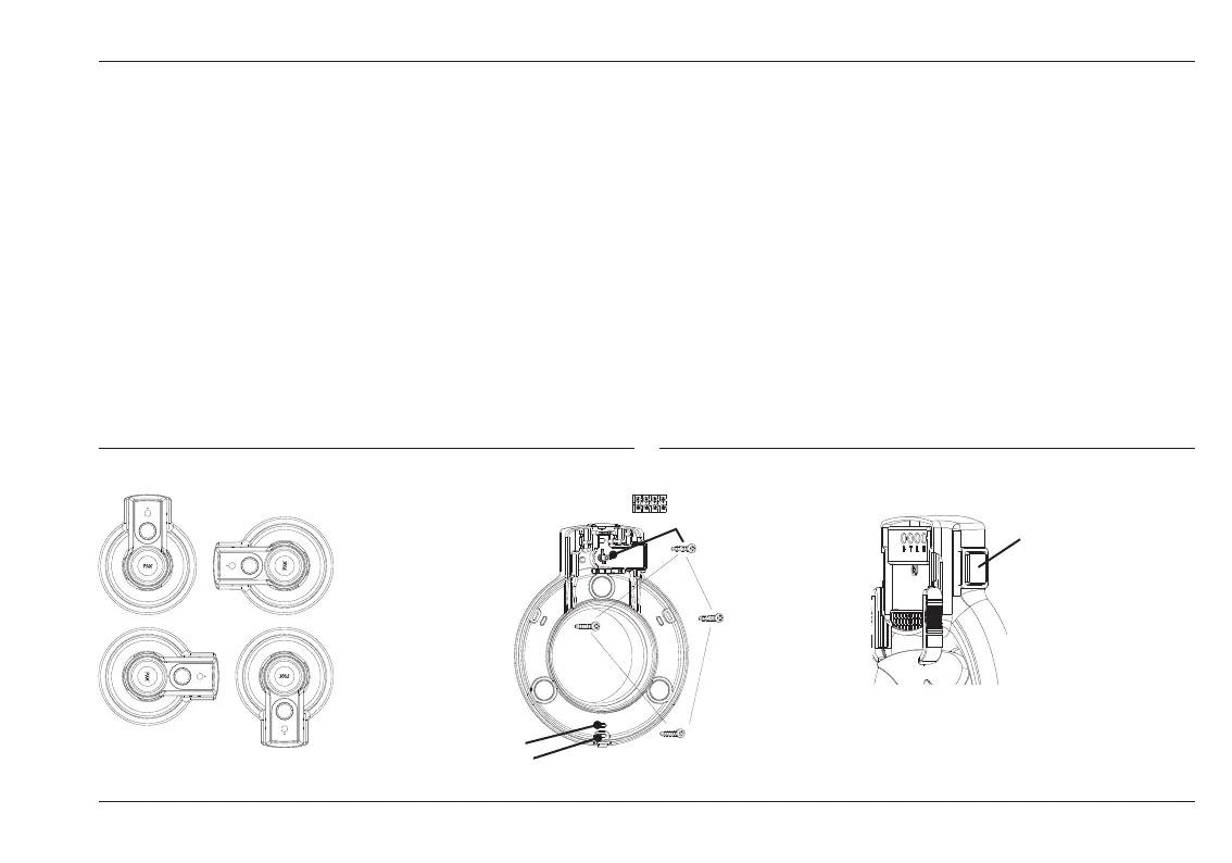
Secure the frame to the structure
The fan may be installed in any position (G)
Secure the frame to the structure with the four screws. The inner holes (H1)
have the same hole pattern as the Pax 200 series fans. This makes it easier
to change to a Pax Passad fan. The outer holes (H2) are used if the size
of the duct limits the space available for rm xing. If there is not enough
space for screw xing, we recommend installing a PAX cover plate or a
Pax assembly frame. Do not forget the screw (H3) under the terminal block.
It is used to adjust the fan with respect to the structure so that the impeller
is centred in the frame.
Connection
According to the standard for domestic products, EN 60335-1, it must be
possible to isolate such products from the electric power supply. One way
is to use a Pax multi-pole switch (M).
For Pax Passad 00, 30 and 31 the Pax multi-pole switch (8104-3) is avalable
as an accessory for retrotting.
Always isolate the product from the electric power supply before doing
any electrical work on it. The fan is designed for 230V AC, 50Hz.
It is double-insulated and must not be grounded.
The following pages show wiring diagrams for each model.
H3
H2
H1
M
G
 Loading...