Page 2
Decide how the units are to be connected. You can either run your own wired network or (with the owner's
permission) share the buildings existing data network. If using the owners network, the system uses IPv6 protocol
and PoE (Power over Ethernet) so the network must support this switch type.
Installation
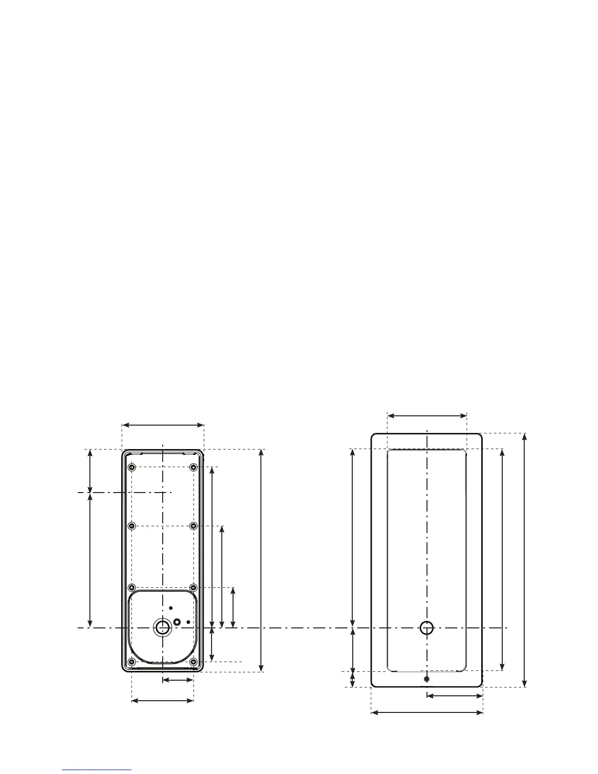
Fixing
106 mm
℄
140 mm
290 mm
320 mm
70 mm
21 mm
The unit is supplied with the surface mount backbox. A ush mount backbox is also available (PN:337-857).
Screws and wall plugs are provided in the tting kit.
SURFACE
BACKBOX
FLUSH
BACKBOX
51 mm
40 mm
44 mm
205 mm
80 mm
130 mm
281 mm
104 mm
℄
A single hole must be drilled for the single data/power connection. Electrical power is supplied via the data cable (PoE)
from the Net2 Entry controller.
1. Determine the height for the camera and then mark and drill the cable hole with reference to the Fixing diagram.
2. Complete the installation of the mounting backbox - Surface or Flush.
3. Connect the Net2 Entry panel to controller.
4. Mount the panel in its backbox.
5. Power up the panel from controller supply (PoE).
The display will ask you to set up an Engineer code. The panel checks to see if any monitors also exist on the
network. Any that are detected will now have the engineer code loaded and will store the panel ID that called them
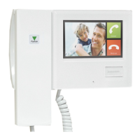
The best height to install the panel is with the camera at eye level This will allow you to see your visitor's face clearly
even when they are wearing a hood or cap.
To achieve the best camera performance, try to mount the panel facing away from direct sun or a bright light source.
This will also help the user to read the LCD display.
30 mm
196 mm
55 mm
Camera
Height
Cable
Hole
235 mm
Where it is not practical to run a patch cable to the rear of the unit, it can be directly wired to the network cable
via the supplied IDC module.
Paxton recommend that the network cable is run to each location and terminated in a network box. A patch
cable should then be used to link the unit to the network. This makes unit replacement or removal for building
maintenance much easier.
NOTE: All dimensions are shown in millimetres to maintain accuracy.