29
A04127
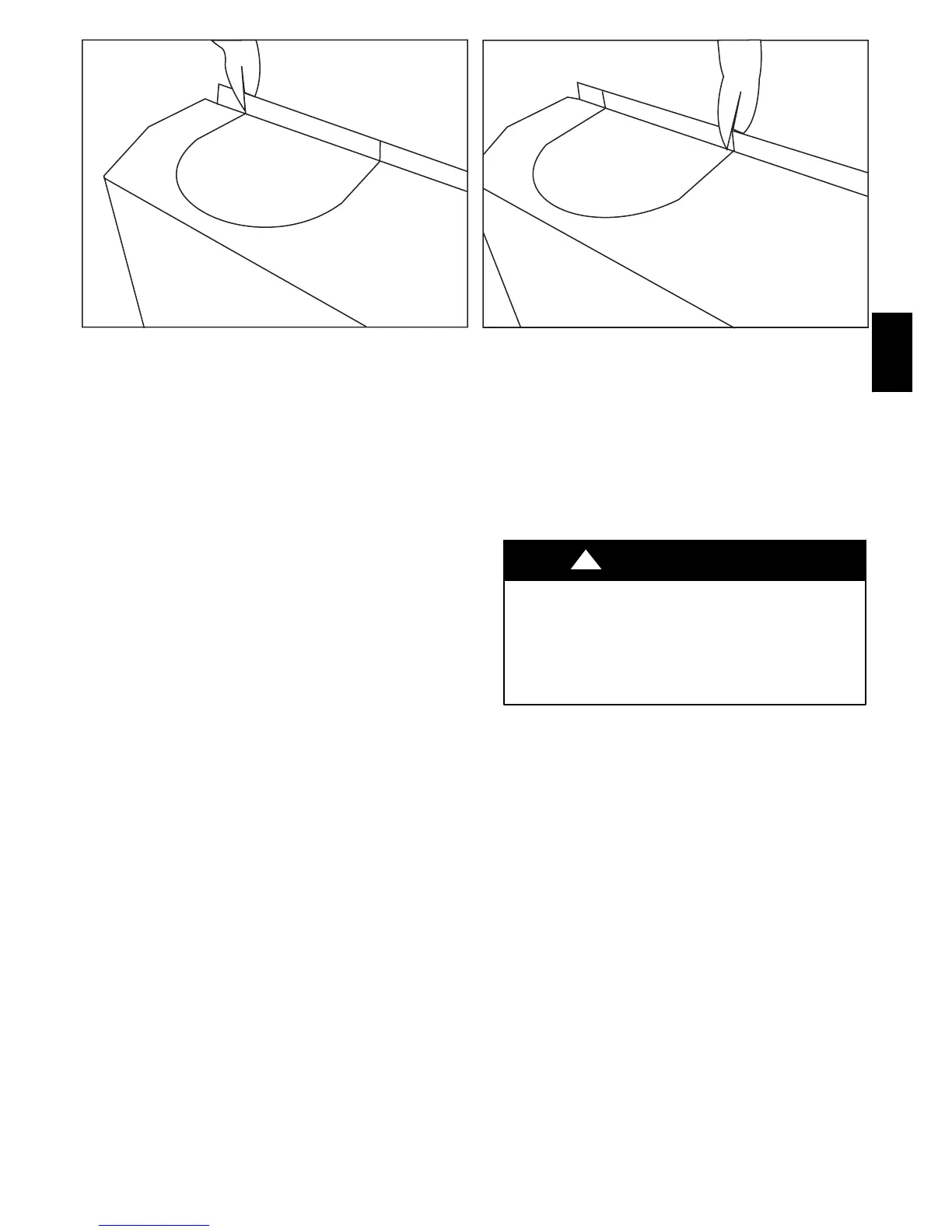
Fig. 28 --- Using Tin Snips to Cut Tie Points
Air for combustion must not be contaminated by halogen
compounds which include chlorides, fluorides, bromides, and
iodides. These compounds are found in many common home
products such as detergent, paint, glue, aerosol spray, bleach,
cleaning solvent, salt, and air freshener, and can cause corrosion
of furnaces and vents. Avoid using such products in the
combustion-- air supply. Furnace use during construction of the
building could cause the furnace to be exposed to halogen
compounds, causing premature failure of the furnace or venting
system due to corrosion.
Vent dampers on any appliance connected to the common vent
can cause condensation and corrosion in the venting system. Do
not use vent dampers on appliances common vented with this
furnace.
ADDITIONAL VENTING REQUIREMENTS
A 4 in. round vent elbow is supplied with the furnace. A 5--in. or
6-- in. vent connector may be required for some model furnaces.
A field--supplied 4--in.--to--5--in. or 4--in.--to--6--in. sheet metal
increaser fitting is required when 5--in. or 6--in. vent connector is
used. See Fig. 33--44 Venting Orientation for approved vent
configurations.
NOTE: Vent connector length for connector sizing starts at
furnace vent elbow. The 4 --in. vent elbow is shipped for upflow
configuration and may be rotated for other positions. Remove the
3 screws that secure vent elbow to furnace, rotate furnace vent
elbow to position desired, reinstall screws. The factory--supplied
vent elbow does NOT count as part of the number of vent
connector elbows.
The vent connector can exit the door through one of 5 locations
on the door.
1. Attach the single wall vent connector to the furnace vent
elbow, and fasten the vent connector to the vent elbow
with at least two field--supplied, corrosion--resistant, sheet
metal screws located 180_ apart.
NOTE: An accessory flue extension KGAFE0112UPH is
available to extend from the furnace elbow to outside the furnace
casing. If flue extension is used, fasten the flue extension to the
vent elbow with at least two field--supplied, corrosion--resistant,
sheet metal screws located 180_ apart. Fasten the vent connector
to the flue extension with at least two field--supplied, corrosion
resistant sheet metal screws located 180_ apart.
2. Vent the furnace with the appropriate connector as shown
in Fig. 33--45.
CUT HAZARD
Failure to follow this caution may result in personal injury.
Sheet metal parts may have sharp edges or burrs.
Use care and wear appropriate protective clothing, safety
glasses and gloves when handling parts and servicing
furnaces.
CAUTION
!
3. Orient the door to determine the correct location of the
door cutout to be removed.
4. Use aviation --type tin snips to remove the correct
U--shaped cut--out in door.
NOTE: If this furnace is equipped with knockouts in the door
for the vent, a number of techniques can be used to remove these
knockouts as seen in Fig. 28 through 32. The knockout in the
bottom of the door is unique due to its flanging and is not easily
removed by first cutting the two tie points at the edge of the door,
using aviation--type tin snips. (See Fig. 28.) A sharp blow to the
rounded end of the knockout (See Fig. 29.) will separate more tie
points and allow the knockout to be pulled loose. (See Fig. 30.)
Remove all burrs and sharp edges.
PG8J/M