EasyManuals Logo

PCB Piezotronics IMI SENSORS 685B0000A10 User Manual

Default Icon
25 pages
To Next Page IconTo Next Page
To Previous Page IconTo Previous Page
Page #10 background imageLoading...
Page #10 background image
PAGE 5
SENSORS AND INSTRUME
NTATION FOR MACHINE
CONDITION MONITORING
Installation and Wiring
Installation
The 685B-Series is designed to be mounted directly on the equipment to be monitored using a four-bolt pattern.
There are also options to retrofit existing 3 bolt pattern installations. (Model 080A209 mounting plate required-
see optional accessories on page 13). Use grease between all surfaces to insure specified frequency response,
otherwise performance will be degraded. The axis of vibration measured by models with internal accelerometers
is perpendicular to the mounting orientation of the unit.
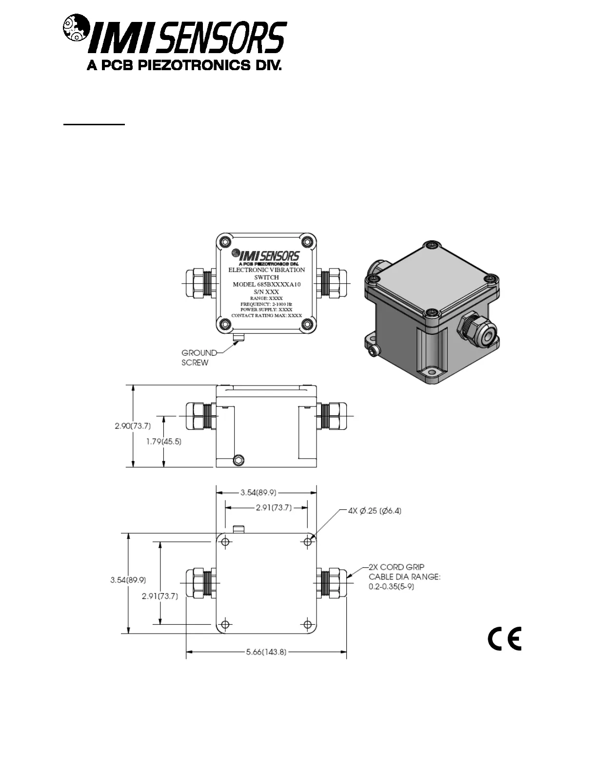
Standard Model Dimension Drawing with Cord Grips
Inch (mm)

Questions and Answers:

Question and Answer IconNeed help?

Do you have a question about the PCB Piezotronics IMI SENSORS 685B0000A10 and is the answer not in the manual?

PCB Piezotronics IMI SENSORS 685B0000A10 Specifications

General IconGeneral
BrandPCB Piezotronics
ModelIMI SENSORS 685B0000A10
CategorySwitch
LanguageEnglish